
Connector

a technology of connecting rods and cooling systems, which is applied in the direction of machines/engines, functional valve types, operating means/releasing devices of valves, etc., can solve the problems that one or more engine lubrication systems, such as the engine lubrication system, may not operate as effectively compared, and the temperature of one or more components of the engine may increase quickly

Active Publication Date: 2021-02-16
FORD GLOBAL TECH LLC
View PDF8 Cites 0 Cited by
  • Summary
  • Abstract
  • Description
  • Claims
  • Application Information

AI Technical Summary

Benefits of technology

The patent text describes certain features of the invention in relation to only one or several aspects or embodiments. However, these features can also be used with other aspects or embodiments of the invention. The technical effect of this is that it avoids unnecessary repetition of effort and text in the specification, making it easier to read and interpret.

Problems solved by technology

When the engine is initially started, and is operating at a reduced temperature, one or more systems of the engine, such as the engine lubrication system, may not operate as effectively compared to when the engine is operating at a normal operating temperature.
However, if a driver of the motor vehicle operates the engine by requesting a large power or torque whilst the engine is heating up, temperatures of one or more components of the engine may increase quickly whilst the engine is supplying the large power or torque.
A conflict therefore exists between controlling the engine cooling system to allow the engine to heat up quickly after a cold start, and providing sufficient cooling when the engine is operating to provide a high power or torque during engine warm-up.

Method used


Image

  • Connector
  • Connector
  • Connector

Examples


Embodiment Construction

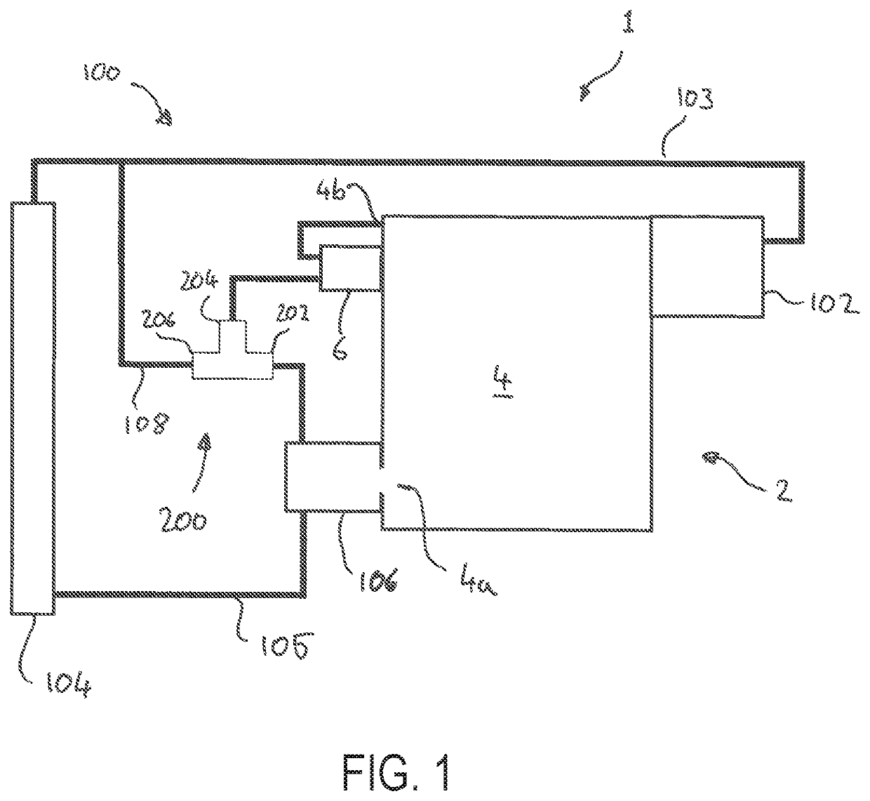
[0029]With reference to FIG. 1, an engine assembly 1, such as for a motor vehicle, comprises an engine 2, having one or more engine housings 4, such as a cylinder block and / or cylinder head, and an engine cooling system 100.

[0030]The engine cooling system 100 comprises a coolant pump 102 for pumping a flow of coolant around the cooling system 100. The coolant pump 102 may be driven, such as directly driven, by the engine 2. Alternatively, the coolant pump 102 may be electrically driven or driven by another engine or motor provided on the vehicle.

[0031]Coolant pumped by the cooling pump 102 may flow through the engine housing 4 in order to cool the engine 2. The coolant may leave the engine housing 4 via a first outlet 4a and flow towards a radiator 104 of the cooling system 100.

[0032]In the radiator 104, heat is rejected from the coolant into a flow of air passing over the radiator 104. The coolant leaving the radiator 104 may return to the coolant pump 102 via a return duct 103 to ...


PUM


Abstract

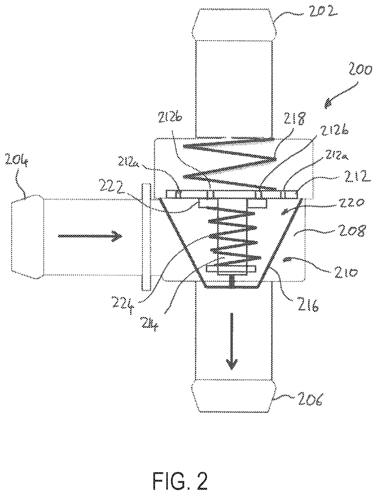
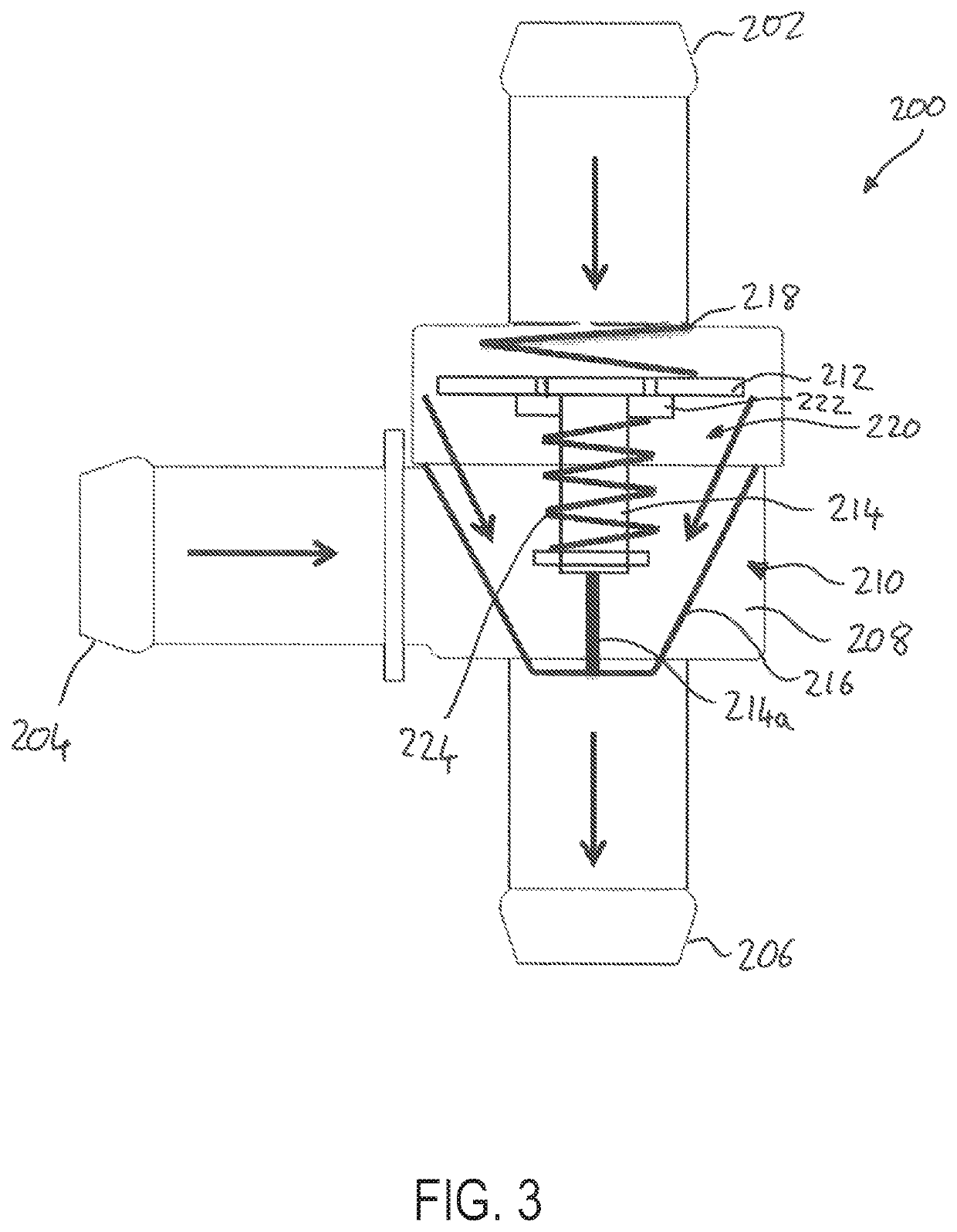
A connector for an engine cooling system is provided. The connector may be located in a chamber with two inlets and an outlet. The connector may include a thermostatic valve. A temperature sensitive element may move the thermostatic valve between an open and closed position. A pressure relief valve may also be incorporated into the thermostatic valve. An engine cooling system comprising the connector is also provided.

Description

CROSS REFERENCE TO RELATED APPLICATION[0001]The present application claims priority to Great Britain patent application No. 1801758.2, filed on Feb. 2, 2018. The entire contents of the above-listed application are hereby incorporated by reference for all purposes.TECHNICAL FIELD[0002]The present disclosure relates to a connector for an engine cooling system and the connector improving engine warm-up.BACKGROUND[0003]Engine cooling systems, including engines of motor vehicles, typically comprise a coolant pump driven by the engine to pump coolant through a housing of the engine, in order to cool the engine. After passing through the engine housing, the coolant is typically directed to flow through a radiator of the cooling system, where heat is rejected from the coolant into a flow of air passing over the radiator.[0004]When the engine is initially started, and is operating at a reduced temperature, one or more systems of the engine, such as the engine lubrication system, may not oper...

Claims


Application Information

Patent Timeline
Patent Type & Authority Patents(United States)
IPC IPC(8): F01P7/16F01P7/12F16K17/02F16K31/00F01P7/14F01P7/02F01P11/02F01P3/22
CPCF01P7/165F01P7/16F16K17/02F16K31/002F01P7/026F01P7/12F01P11/0295F01P2003/2214F01P2007/146F01P2025/50F01P2060/04F01P2060/08F01P2060/14F16K11/10
Inventor LECK, CHRISSCHOLTES, DUNCAN
Owner FORD GLOBAL TECH LLC
Learn More