Check patentability & draft patents in minutes with Patsnap Eureka AI!

Vapor chamber structure

a technology of vapor chamber and structure, which is applied in the direction instruments, and semiconductor/solid-state device details, etc., can solve the problems of affecting the efficiency of lighting and heating apparatus, the remaining space for arrangement of heat dissipation components is quite limited, and the heat cannot be hardly properly dissipated

Active Publication Date: 2021-03-16
ASIA VITAL COMPONENTS SHENZHEN CO LTD
View PDF20 Cites 1 Cited by
  • Summary
  • Abstract
  • Description
  • Claims
  • Application Information

AI Technical Summary

Benefits of technology

[0010]The vapor chamber structure of the present invention is a very thin structure, which can be installed in a limited space and securely assembled with a heat source. After assembled, the internal chamber of the vapor chamber can still keep in an airtight state.

Problems solved by technology

Otherwise, the heat can be hardly properly dissipated.
Moreover, the current electronic apparatus has become thinner and thinner and lighter and lighter.
Therefore, the remaining space for arrangement of the heat dissipation components is quite limited.
Due to the limitation of the space, after the latch device is overlaid on the vapor chamber, the height may exceed the height of the preset arrangement space.
In case the vapor chamber is directly locked on the heat source (the calculation unit (CPU)) without using the latch device, the vapor chamber will be damaged to lose its airtight state.
Also, due to the limitation of the space, it is impossible to additionally install any radiating fin or cooling fan in the electronic apparatus.
Therefore, it has become a critical issue how to arrange the heat dissipation components in the limited space and tightly secure the heat dissipation components on the heat source.

Method used


Image

  • Vapor chamber structure
  • Vapor chamber structure
  • Vapor chamber structure

Examples


Embodiment Construction

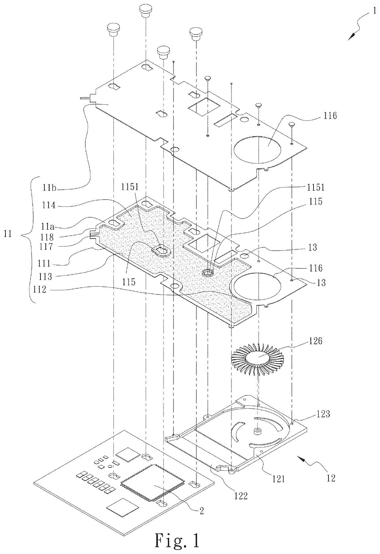
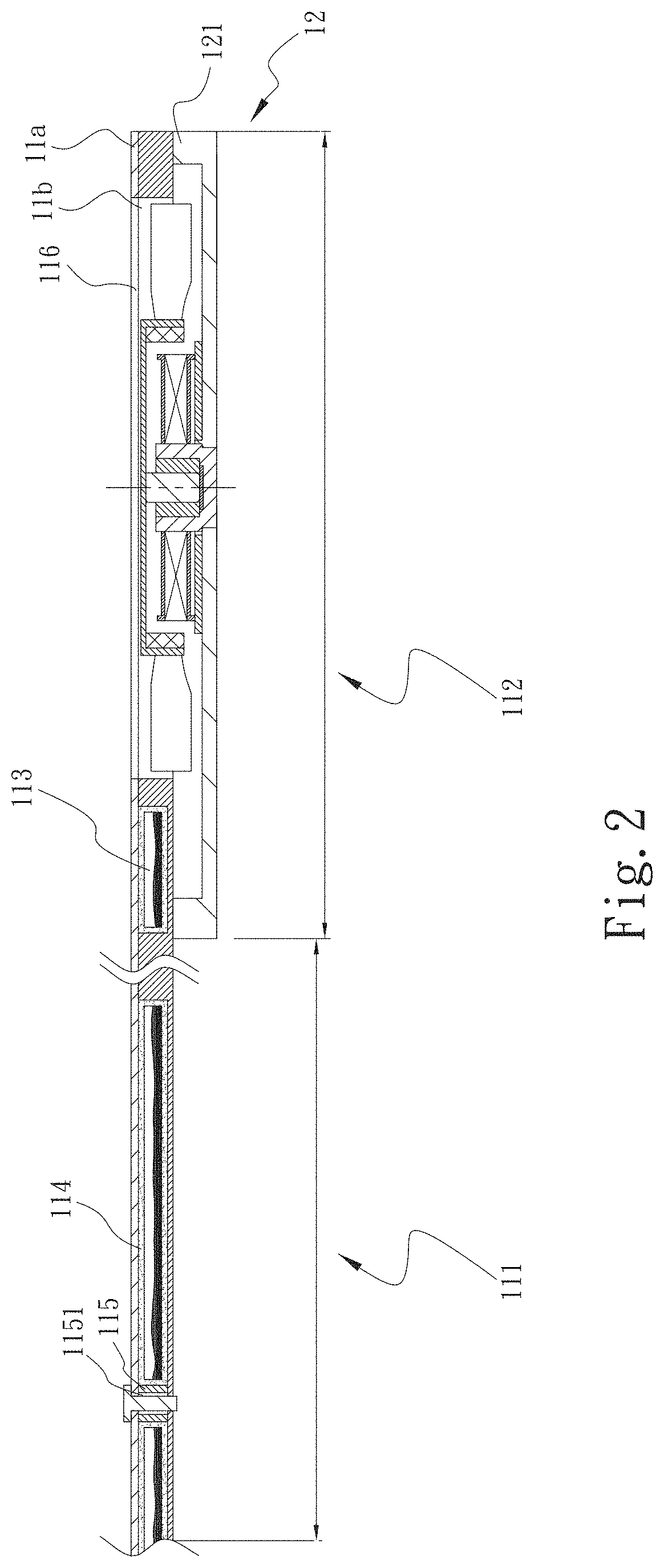
[0021]Please refer to FIGS. 1 and 2. FIG. 1 is a perspective exploded view of a first embodiment of the vapor chamber structure of the present invention. FIG. 2 is a sectional assembled view of the first embodiment of the vapor chamber structure of the present invention. As shown in the drawings, the vapor chamber structure 1 of the present invention includes a main body 11, a fan 12 and multiple perforations 13.

[0022]The main body 11 is a flat-plate body and has a heat absorption section 111, a heat dissipation section 112 and a chamber 113. The heat absorption section 111 and the heat dissipation section 112 are respectively horizontally disposed on left and right sides of the main body 11. The heat absorption section 111 is attached to at least one heat source 2. The chamber 113 is positioned at the heat absorption section 111 and partially extends to the heat dissipation section 112. The chamber 113 has a capillary structure 114 and at least one perforated section 115. The perfo...


PUM


Abstract

A vapor chamber structure includes a main body, a fan and perforations. The main body has a heat absorption section, a heat dissipation section and a chamber. The heat absorption section and the heat dissipation section are respectively horizontally disposed on left and right sides of the main body. The heat absorption section is attached to at least one heat source. The chamber is positioned at the heat absorption section and partially extends to the heat dissipation section. The chamber has a capillary structure and at least one perforated section. The perforated section is connected between an upper side and a lower side of the chamber. The fan is disposed on one side of the heat dissipation section. The perforations are formed through the parts of the main body, which parts are free from the chamber and the parts of the main body, where the perforated section is disposed.

Description

[0001]The present application is a Continuation-in-Part of U.S. patent application Ser. No. 15 / 183,792 filed on Jun. 16, 2016.BACKGROUND OF THE INVENTION1. Field of the Invention[0002]The present invention relates generally to a vapor chamber structure, and more particularly to a thinned vapor chamber structure connected with a cooling fan.2. Description of the Related Art[0003]The current handheld devices, tablets, ultrathin notebooks, mobile devices and the like electronic apparatuses have become thinner and thinner. With the enhancement of the working performance, the power of the internal calculation unit (CPU) of the electronic apparatus is increased. With the increase of the power of the calculation unit (CPU), the heat generated by the calculation unit (CPU) is increased. The heat must be forcedly dissipated by a heat dissipation component. Otherwise, the heat can be hardly properly dissipated. Therefore, it is necessary to arrange heat dissipation components such as heat pip...

Claims


Application Information

Patent Timeline
Patent Type & Authority Patents(United States)
IPC IPC(8): F28D15/02F28D15/04H01L23/427F28F21/08G06F1/20H01L23/467F28D21/00H01L23/367
CPCF28D15/0275F28D15/0233F28D15/046F28F21/083F28F21/086G06F1/203H01L23/427H01L23/467F28D2021/0028F28F2250/08G06F2200/201H01L23/3672
Inventor HSIEH, KUO-CHUNTSAI, TSUNG-HSIEN
Owner ASIA VITAL COMPONENTS SHENZHEN CO LTD
Features
  • R&D
  • Intellectual Property
  • Life Sciences
  • Materials
  • Tech Scout
  • Unparalleled Data Quality
  • Higher Quality Content
  • 60% Fewer Hallucinations
Learn More