Seat moving structure for utility vehicle

a technology for moving structures and utility vehicles, applied in the direction of movable seats, vehicle components, vehicle arrangements, etc., can solve the problems of difficult to increase the amount of seat slide, and achieve the effect of easy suppression of interferen

Active Publication Date: 2021-03-30
KAWASAKI MOTORS LTD
View PDF26 Cites 0 Cited by
  • Summary
  • Abstract
  • Description
  • Claims
  • Application Information

AI Technical Summary

Benefits of technology

[0004]The present invention has been made in view of the above-mentioned drawbacks, and it is an object of the present invention to provide a seat moving structure for a utility vehicle where a seat slide load can be reduced while increasing a seat slide amount.
[0037]With the configuration (12), it is possible to easily suppress interference between the rollers and a top wall of the bracket having the U-shaped cross section, and the seat rail contact portion assembled into the sub assembly can be formed in a compact shape in the vertical direction. With such a configuration, the moving structure of the seat can be formed in a compact shape in the vertical direction.

Problems solved by technology

With the structure disclosed in US2016 / 0176316A1, a seat slide amount which is a moving amount of the seat in the longitudinal direction depends on a length of the elongated hole in a long axis direction and hence, it is difficult to increase the seat slide amount.

Method used


Image

  • Seat moving structure for utility vehicle
  • Seat moving structure for utility vehicle
  • Seat moving structure for utility vehicle

Examples


first embodiment

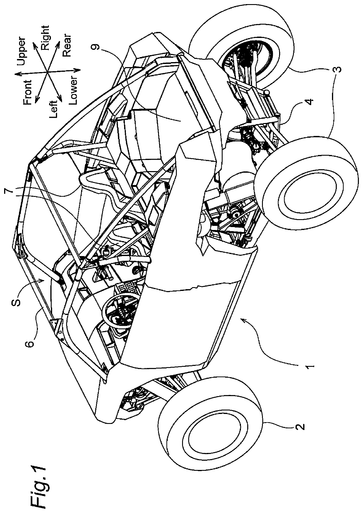
[0052]In FIG. 1, a utility vehicle 1 includes: a vehicle body frame 4; right and left front wheels 2 disposed on a front end of the vehicle body frame 4; and right and left rear wheels 3 disposed on a rear end of the vehicle body frame 4. A riding space S is positioned between the front wheels 2 and the rear wheels 3 in a longitudinal direction, and is surrounded by a ROPS 6. A pair of right and left independent type seats 7 is disposed in the inside of the riding space S. The utility vehicle 1 further includes a cargo bed 9 behind the riding space S, and an engine (not shown in the drawing) is disposed below the cargo bed 9. The ROPS is the abbreviation of rollover protective structure.

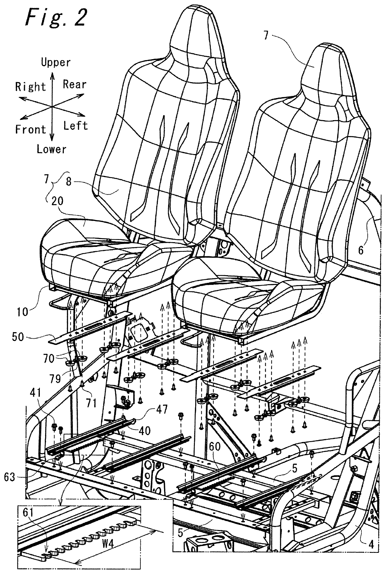
[0053]FIG. 2 is an exploded perspective view showing the attachment structure for attaching the seats 7 on the vehicle body frame 4. As shown in FIG. 2, a pair of front and rear seat cross members 5 extending in a vehicle width direction is mounted on an upper portion of the vehicle body frame 4. A p...

second embodiment

[0121]A seat moving structure for a utility vehicle according to a second embodiment is described with reference to FIG. 7 to FIG. 11. In the description made hereinafter, the technical feature which makes the second embodiment differ from the first embodiment is mainly described, and members identical with the corresponding members of the first embodiment are given the same symbols and the repeated description of these members is omitted.

[0122]FIG. 7 is a perspective view showing a seat moving structure 200 according to the second embodiment, and a seat back 8 and a seat cushion 20 are shown in a transparent manner. As shown in FIG. 7, the seat moving structure 200 includes roller assemblies 210 which form a seat rail contact portion of the present invention, and seat rails 230 which form a rail support surface portion of the present invention. That is, the seat moving structure 200 differs from the seat moving structure 100 of the first embodiment with respect to the technical fea...


PUM


Abstract

A seat moving structure for a utility vehicle includes a seat and a seat rail for guiding movement of the seat in a longitudinal direction of the seat. The seat has a seat rail contact portion which is in contact with the seat rail. The seat rail has a rail support surface portion which supports the seat rail contact portion from below. The seat rail contact portion is made of a resin. The seat is movably supported in a line contact state or in a point contact state in the longitudinal direction of the seat on the rail support surface portion by the seat rail contact portion.

Description

BACKGROUND OF THE INVENTIONField of the Invention[0001]The present invention relates to a seat moving structure for a utility vehicle.Description of the Related Art[0002]US2016 / 0176316A1 discloses, as a seat moving structure for a utility vehicle, a structure where a seat attachment portion in which an elongated hole extending in a longitudinal direction is vertically formed in a penetrating manner is disposed at four corners of the seat, the seat is placed on a seat support portion of a vehicle body by way of the seat attachment portions, and seat guide portions formed on the seat support portions are made to pass through the elongated holes. With such a structure, the positions of the elongated holes are restricted in the longitudinal direction by the seat guide portions. Accordingly, the seat moving structure for a utility vehicle is configured such that the seat is slidable in the longitudinal direction.SUMMARY OF THE INVENTION[0003]With the structure disclosed in US2016 / 0176316...

Claims


Application Information

Patent Timeline
Patent Type & Authority Patents(United States)
IPC IPC(8): B60N2/07B60N2/38
CPCB60N2/0722B60N2/38
Inventor MAEDA, KAZUHIRO
Owner KAWASAKI MOTORS LTD
Why Eureka
Try Eureka