Disk replacing device

A technology of disc and lifting device, which is applied in recording information storage, instruments, etc., can solve the problem of 8cm small-diameter disc 223 falling into the device, and achieve the effect of reducing the number of parts, realizing common use, and preventing mutual contact.

Inactive Publication Date: 2004-02-25
PANASONIC CORP
View PDF0 Cites 0 Cited by
  • Summary
  • Abstract
  • Description
  • Claims
  • Application Information

AI Technical Summary

Problems solved by technology

[0012] Also, for changing the disk, after the tray 215 is opened, since the opening 222 in the front of the dev

Method used


Image

  • Disk replacing device
  • Disk replacing device
  • Disk replacing device

Examples


Embodiment Construction

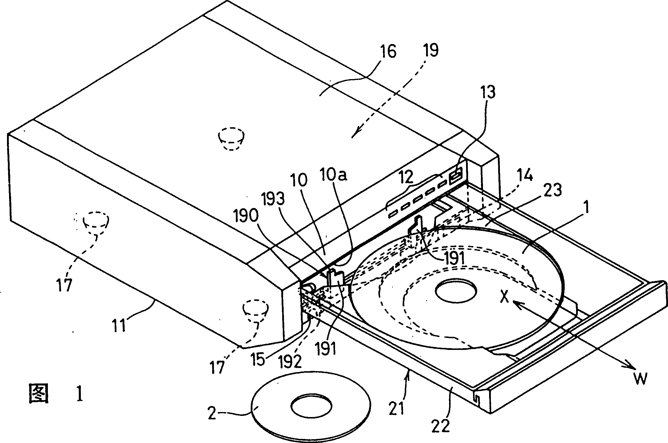
[0086] Below, refer to Figures 1 to Figure 42 A description will be given of an example of a disc changing device according to an embodiment of the present invention.

[0087] In Figure 1, 1 is a disc with a large diameter of 12 cm, and 2 is a disc with a small diameter of 8 cm. A front panel 10 is installed on the bottom plate body 11 and the like, and a sequence number key 12, an open / close key 13, a playback key 14, and a stop key 15 are provided on the front part thereof. 16 is a housing for covering the disk replacement device 19 of the present invention, and 17 is an insulating member provided on the side of the bottom plate body 11. 22 is a tray base projecting from the opening 10a of the front panel 10. 23 is a tray that is slidable in the direction of arrow W-X guided by the tray base 22, and on the tray 23, the replaced discs 1 and 2 are supplied.

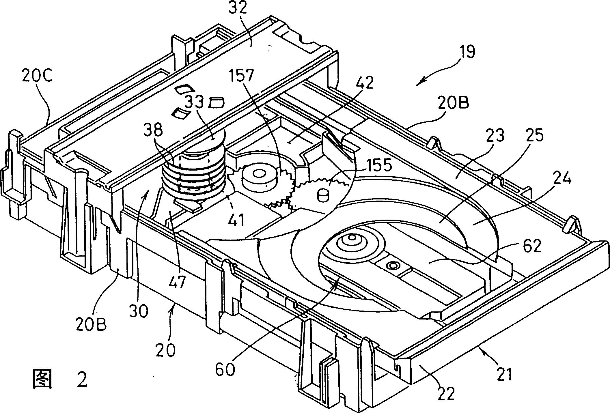
[0088] In Figure 2, Figure 4 , Figure 33 with Figure 34 Among them, the device body 20 is composed of a bottom plate 20...


PUM


Abstract

According to the present inventive diskette changing device, an elevating means for elevating and lowering the spindles constituting the disc holding means and a disc playing means is configured so that a single part simultaneously performs these operations. Since the same part is driven to perform these operations rather than the traditional mode that they they are drived by their own elevating mechanism, connection mechanism, and locking mechanism, elevating and lowering timings for the spindles and the disc playing means can be easily matched to enable the elevation and lowering without changes in the gap between a played disc being elevated or lowered and held discs in a housing section, thereby preventing the discs being elevated or lowered from contacting with each other, making the structure of means simple and miniaturization, and reducing the load change and the noise.

Description

Technical field [0001] The present invention relates to a disc changing device which contains a plurality of discs and arbitrarily selects the discs from the loaded discs for recording and reproducing. Background technique [0002] In the conventional disk changing device, the disk holding device adopts a structure in which a plurality of auxiliary trays are placed in a feeder with a plurality of racks. The structure of the vertical drive device that selects an arbitrary disk position is the same as that described above. The feeder, multiple auxiliary trays, and multiple discs are driven up and down as a whole. [0003] However, in the conventional disk changing device, when the disk holding device is driven and the vertical drive device that selects arbitrary disk positions is driven, it has multiple racks and multiple auxiliary trays and multiple disks. The disc holding device for the entire disc drive is very heavy, which will cause the vertical drive motor to consume a lot of...

Claims


Application Information

Patent Timeline
IPC IPC(8): G11B17/22
CPCG11B17/22
Inventor 中村政彦三好清三森冈幸生太田武志
Owner PANASONIC CORP
Why Eureka
Try Eureka