Waveguide display device

a display device and waveguide technology, applied in the field of augmented reality display devices, can solve the problems of inability to perfectly match the optical display system with the pupil of the user, the display system cannot wear-ability as a spectacle, and the size of the conventional optical display system is limited, so as to achieve uniform image brightness, the effect of uniform image brightness

Active Publication Date: 2021-03-30
SHANGHAI NORTH OCEAN PHOTONICS CO LTD
View PDF16 Cites 16 Cited by
  • Summary
  • Abstract
  • Description
  • Claims
  • Application Information

AI Technical Summary

Benefits of technology

[0008]Another advantage of the invention is to a waveguide display device, wherein the grating structure is modulated to provide a uniform brightness of the image being seen by the user, even though there is any relative displacement of the AR spectacle with respect to the user eyes, the brightness of the image will remain uniform and stable (the brightness in the window eyebox is uniform).
[0009]Additional advantages and features of the invention will become apparent from the description which follows, and may be realized by means of the instrumentalities and combinations particular point out in the appended claims.
[0010]According to the present invention, the foregoing and other objects and advantages are attained by a waveguide display device comprising a waveguide substrate, an input diffractive optical element and an output diffractive optical element.
[0011]The input diffractive optical element is arranged for coupling an output light of a light projector to the waveguide substrate.
[0012]The waveguide substrate is arranged for reflecting light from the input diffractive optical element by means of total internal reflection toward the output diffractive optical element.
[0013]The output diffractive optical element for partially diffracting and partially transmitting light reflected by the waveguide substrate via the total internal reflection, wherein at each light reflection, the diffracted light is projected out of the waveguide substrate toward a user eye, and the transmitted light is continuously reflected within the waveguide substrate by means of total internal reflection until the light is diffracted out of the waveguide substrate for completing an exit pupil expansion.

Problems solved by technology

However, since the display system is constructed by conventional optical components, it is limited by the overall optical distance to minimize a thinness of the display system.
The wear-ability of the display system as a spectacle cannot be achieved.
Furthermore, due to the constraints of the Lagrangian invariant, the size of the conventional optical display system is limited, and the optical display system cannot perfectly match with the pupils of the user.
Based on the exit pupil expansion in the waveguide display device, the light energy in the waveguide is gradually attenuated during the image sequencing output process, and the diffraction efficiency of the input-and-output optical components on the diffraction waveguide is low, such that the system energy is significantly lost.
However, the gradient coating process is complicated and the manufacturing cost is relatively high since the process is performed on a single optical waveguide.

Method used


Image

  • Waveguide display device
  • Waveguide display device
  • Waveguide display device

Examples


Embodiment Construction

[0056]The following description is disclosed to enable any person skilled in the art to make and use the present invention. Preferred embodiments are provided in the following description only as examples and modifications will be apparent to those skilled in the art. The general principles defined in the following description would be applied to other embodiments, alternatives, modifications, equivalents, and applications without departing from the spirit and scope of the present invention.

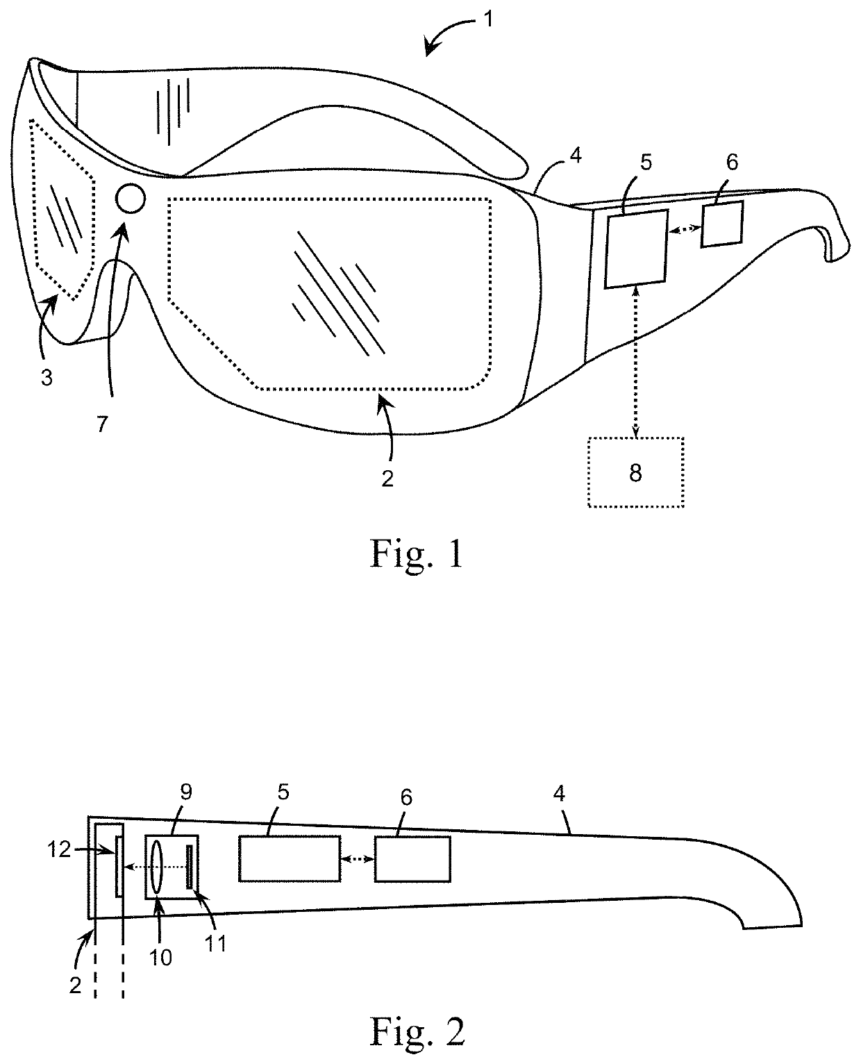
[0057]Referring to FIG. 1 of the drawings, an augmented reality device for being worn by a user is illustrated, wherein the augmented reality wearable device comprises a spectacle frame 4 and a waveguide display device. The spectacle frame 4 comprises two spectacle arms and a bridge, and an augmented reality system 1, which is based on an optical waveguide. The augmented reality system 1 comprises a waveguide display device which comprises two optical waveguides, i.e. a left-eye optical waveguide...


PUM

PropertyMeasurementUnit
degree of freedomaaaaaaaaaa
total internal reflectionaaaaaaaaaa
brightnessaaaaaaaaaa

Abstract

An optical waveguide includes an input diffractive optical element arranged for being aligned with an optical projector for diffracting light beams therefrom, a waveguide substrate n, and an output diffractive optical element. Light beams diffracted by the output diffractive optical element are coupled out of the waveguide substrate towards users' eyes. The output diffractive optical element has an effective area arranged to maintain a constant output flux per unit area therein for providing an uniform image in brightness when the image is being projected out of the waveguide substrate.

Description

NOTICE OF COPYRIGHT[0001]A portion of the disclosure of this patent document contains material which is subject to copyright protection. The copyright owner has no objection to any reproduction by anyone of the patent disclosure, as it appears in the United States Patent and Trademark Office patent files or records, but otherwise reserves all copyright rights whatsoever.BACKGROUND OF THE PRESENT INVENTIONField of Invention[0002]The present invention relates to an augmented reality display device (AR) or a head-up display device, and more particularly to a waveguide display device, which is able to increase a brightness uniformity of a pupil output image and to improve a system output efficiency.Description of Related Arts[0003]Augmented reality is a new technology to provide an interactive experience of a real world environment where virtual objects are resided in the real world in a real time manner. Accordingly, a computer-generated prompt message, virtual object, or virtual scene...

Claims


Application Information

Patent Timeline
Patent Type & Authority Patents(United States)
IPC IPC(8): G02B27/01F21V8/00G02B27/00
CPCG02B27/0172G02B6/0016G02B6/0036G02B27/0081G02B2027/0118G02B2027/0138G02B2027/0178G02B5/1819G02B6/4214
Inventor LOU, XINYEHUANG, HELIN, TAO
Owner SHANGHAI NORTH OCEAN PHOTONICS CO LTD
Why Eureka
Try Eureka