Capacitive discharge welding system

a discharge welding and capacitive technology, applied in the direction of discharge welding, welding apparatus, manufacturing tools, etc., can solve the problems of large equipment requirements, excessive cost, and limited broader application of the technology, and achieve the effect of preventing the saturation of the iron core transformer

Active Publication Date: 2021-04-06
EDISON WELDING INSTITUTE INC
View PDF4 Cites 0 Cited by
  • Summary
  • Abstract
  • Description
  • Claims
  • Application Information

AI Technical Summary

Benefits of technology

[0006]In accordance with one aspect of the present invention, a first capacitive discharge welding system is provided. This capacitive discharge welding system includes at least one capacitive discharge-based power supply, wherein the capacitive discharge-based power supply is adapted to provide alternate polarity pulses from a first weld to a subsequent weld, and wherein the capacitive discharge-based power supply is adapted to be compatible with iron-core transformers used for alternating current resistance welding; a polarity switching network, wherein the polarity switching network includes at least two sets of silicon-controlled rectifiers, and wherein the at least two sets of silicon-controlled rectifiers are arranged in pairs for facilitating current flow in alternate directions; and a pair of engageable properly biased shunt diodes, wherein the pair of engageable properly biased shunt diodes are operative to shunt a reflected current, and wherein shunting the reflected current protects the silicon controlled rectifiers when the system is in use.
[0007]In accordance with another aspect of the present invention, a second capacitive discharge welding system is provided. This capacitive discharge welding system includes at least one capacitive discharge-based power supply, wherein the capacitive discharge-based power supply is adapted to provide alternate polarity pulses from a first weld to a subsequent weld, and wherein the capacitive discharge-based power supply is adapted to be compatible with iron-core transformers used for alternating current resistance welding; at least one iron core transformer adapted to receive electrical discharges from the capacitive discharge-based power supply, wherein the iron-core transformer includes 128 sets of windings ratios having values ranging from 75:1 up to 1625:1, and having maximum step changes of about 5%; a polarity switching network, wherein the polarity switching network includes at least two sets of silicon-controlled rectifiers, and wherein the at least two sets of silicon-controlled rectifiers are arranged in pairs for facilitating current flow in alternate directions; and a pair of engageable properly biased shunt diodes, wherein the pair of engageable properly biased shunt diodes are operative to a shunt reflected current, and wherein shunting the reflected current protects the silicon-controlled rectifiers when the system is in use.
[0008]In accordance with still another aspect of the present invention, a third capacitive discharge welding system is provided. This capacitive discharge welding system includes at least one capacitive discharge-based power supply that is adapted to provide alternate polarity pulses from a first weld to a subsequent weld, and to be compatible with iron-core transformers used for alternating current resistance welding; at least one iron core transformer adapted to receive electrical discharges from the capacitive discharge-based power supply; a polarity switching network that includes at least two sets of silicon-controlled rectifiers that are arranged in pairs for facilitating current flow in alternate directions; a pair of engageable, properly biased shunt diodes that are operative to shunt a reflected current for protecting the silicon-controlled rectifiers when the system is in use; and a control network configured for simultaneous engagement of the properly biased shunt diodes and firing the silicon-controlled rectifiers for current flow; and tracking polarity for assuring that subsequent pulses use opposite direction current flow for preventing saturation of the iron core transformer.

Problems solved by technology

However, broader application of the technology has been limited by a number of factors including: (i) large scale of required equipment (e.g., physical size of the power supplies); (ii) excessive cost; (iii) and limited system flexibility.
Particularly problematic are the types of transformers typically used with CD welding systems.
In such systems, the delivered power is notionally unipolar, thereby preventing the use of more flexible stacked core transformers.
The result is that there is often insufficient matching between capabilities of the system power supply and the requirements of the application for which the welding system is to be used.

Method used


Image

  • Capacitive discharge welding system
  • Capacitive discharge welding system
  • Capacitive discharge welding system

Examples


Embodiment Construction

[0019]Exemplary embodiments of the present invention are now described with reference to the Figures. Although the following detailed description contains many specifics for purposes of illustration, a person of ordinary skill in the art will appreciate that many variations and alterations to the following details are within the scope of the invention. Accordingly, the following embodiments of the invention are set forth without any loss of generality to, and without imposing limitations upon, the claimed invention.

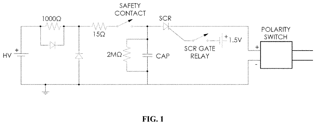
[0020]The present invention provides various enhancements to conventional capacitive discharge (CD) welding systems. Conventional CD systems typically include a high voltage power supply (e.g., up to ˜3500V) coupled with a series of capacitors for storing energy. Welding occurs by discharge of the capacitors through a welding transformer (for impedance matching) into a workpiece (e.g., a weld nut or other part). The output of the capacitors in conventional systems is unip...


PUM

PropertyMeasurementUnit
voltageaaaaaaaaaa
polarityaaaaaaaaaa
current flowaaaaaaaaaa

Abstract

A capacitive discharge welding system includes at least one capacitive discharge-based power supply that is adapted to provide alternate polarity pulses from a first weld to a subsequent weld, and to be compatible with iron-core transformers used for alternating current resistance welding; at least one iron core transformer adapted to receive electrical discharges from the capacitive discharge-based power supply; a polarity switching network that includes at least two sets of silicon controlled rectifiers that are arranged in pairs for facilitating current flow in alternate directions; a pair of engagable, properly biased shunt diodes that are operative to shunt reflected current for protecting the silicon controlled rectifiers when the system is in use; and a control network configured for simultaneous engagement of the properly biased shunt diodes and firing the silicon controlled rectifiers for current flow; and tracking polarity for assuring that subsequent pulses use opposite direction current flow for preventing saturation of the iron core transformer.

Description

CROSS-REFERENCE TO RELATED APPLICATIONS[0001]This patent application claims the benefit of U.S. Provisional Patent Application Ser. No. 62 / 348,463 filed on Jun. 10, 2016 and entitled “Capacitive Discharge Welding System”, the disclosure of which is hereby incorporated by reference herein in its entirety and made part of the present U.S. utility patent application for all purposes.BACKGROUND OF THE INVENTION[0002]The described invention relates in general to resistance and solid state solid-state welding systems and the components thereof, and more specifically to a welding system that includes a capacitive discharge based power supply coupled with a polarity reversing firing mechanism and iron-core transformer arrangement for providing a fine level of impedance matching between capacitive-based stored energy and a secondary resistive / inductive load of a workpiece.[0003]Capacitive discharge (CD) welding is a variation of resistance projection welding, wherein electrical power is stor...

Claims


Application Information

Patent Timeline
Patent Type & Authority Patents(United States)
IPC IPC(8): B23K11/26B23K11/36B23K11/24
CPCB23K11/26B23K11/24B23K11/36
Inventor GOULD, JERRY E.LEWIS, SAMUEL
Owner EDISON WELDING INSTITUTE INC
Why Eureka
Try Eureka