Electrostatic discharge circuit using inductor-triggered silicon-controlled rectifier

a technology of inductance-triggered silicon-controlled rectifiers and electrostatic discharge circuits, which is applied in emergency protective circuit arrangements, emergency protection circuit arrangements for limiting excess voltage/current, transmission, etc., and can solve problems such as shrinking physical size, reducing the service life of integrated circuits, and increasing the risk of electrostatic discharge pulses

Inactive Publication Date: 2011-08-25
TAIWAN SEMICON MFG CO LTD
View PDF2 Cites 49 Cited by
  • Summary
  • Abstract
  • Description
  • Claims
  • Application Information

AI Technical Summary

Problems solved by technology

A radio frequency (RF) receiver connected to an antenna is susceptible to damaging electrostatic discharge (ESD) pulses from its operating environment.
As integrated circuits, including RF receivers, shrink in physical size, the integrated circuits are becoming more susceptible to ESD because of its smaller fabrication geometry.
However, when operating at high frequency, such as five (5) GHz, the parasitic impedance of traditional ESD protection circuits can distort and deteriorate signal integrity.

Method used


Image

  • Electrostatic discharge circuit using inductor-triggered silicon-controlled rectifier
  • Electrostatic discharge circuit using inductor-triggered silicon-controlled rectifier
  • Electrostatic discharge circuit using inductor-triggered silicon-controlled rectifier

Examples


Embodiment Construction

This description of the exemplary embodiments is intended to be read in connection with the accompanying drawings, which are to be considered part of the entire written description. In the description, relative terms such as “lower,”“upper,”“horizontal,”“vertical,”“above,”“below,”“up,”“down,”“top” and “bottom” as well as derivative thereof (e.g., “horizontally,”“downwardly,”“upwardly,” etc.) should be construed to refer to the orientation as then described or as shown in the drawing under discussion. These relative terms are for convenience of description and do not require that the apparatus be constructed or operated in a particular orientation. Terms concerning electrical communications and the like, such as, “coupled” and “electrically coupled” or “electrically connected,” refer to a relationship wherein nodes communicate with one another either directly or indirectly through intervening structures, unless described otherwise.

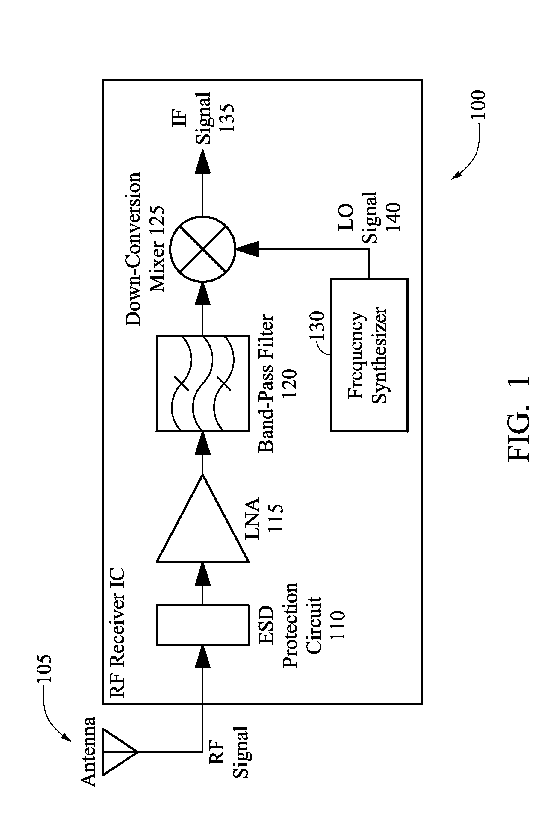
FIG. 1 is a block diagram that illustrates a radio fr...


PUM


Abstract

A representative electrostatic discharge (ESD) protection circuit includes a silicon-controlled rectifier comprising an alternating arrangement of a first P-type semiconductor material, a first N-type semiconductor material, a second P-type semiconductor material and a second N-type semiconductor material electrically coupled between an anode and a cathode. The anode is electrically coupled to the first P-type semiconductor material and the cathode is electrically coupled to the second N-type semiconductor material. The ESD protection circuit further includes an inductor electrically coupled between the anode and the second P-type semiconductor material or between the cathode and the first N-type semiconductor material.

Description

TECHNICAL FIELDThe present disclosure is generally related to electrical circuits, and more particularly to electrostatic discharge protection circuits.BACKGROUNDA radio frequency (RF) receiver connected to an antenna is susceptible to damaging electrostatic discharge (ESD) pulses from its operating environment. As integrated circuits, including RF receivers, shrink in physical size, the integrated circuits are becoming more susceptible to ESD because of its smaller fabrication geometry. There are various traditional methods of shunting ESD to protect integrated circuits including using complementary metal oxide semiconductor (CMOS) or bipolar clamp diodes. However, when operating at high frequency, such as five (5) GHz, the parasitic impedance of traditional ESD protection circuits can distort and deteriorate signal integrity.Desirable in the art is an improved ESD protection circuit.SUMMARYA representative electrostatic discharge (ESD) protection circuit includes a silicon-control...

Claims


Application Information

Patent Timeline
Patent Type & Authority Applications(United States)
IPC IPC(8): H04B1/00H01L27/06H01L23/60
CPCH01L27/0262
Inventor KER, MING-DOLIN, CHUN-YU
Owner TAIWAN SEMICON MFG CO LTD
Why Eureka
Try Eureka