

Light-adjusting and current-limiting control circuit
a control circuit and current limit technology, applied in the direction of electric variable regulation, process and machine control, instruments, etc., can solve the problems of low stability and precision, high manufacturing and maintenance costs of current commercial current limit circuits, and high cost of employing operational amplifiers. , to achieve the effect of low cost, good precision and small siz
- Summary
- Abstract
- Description
- Claims
- Application Information
AI Technical Summary
Benefits of technology
Problems solved by technology
Method used
Image

Examples
first embodiment
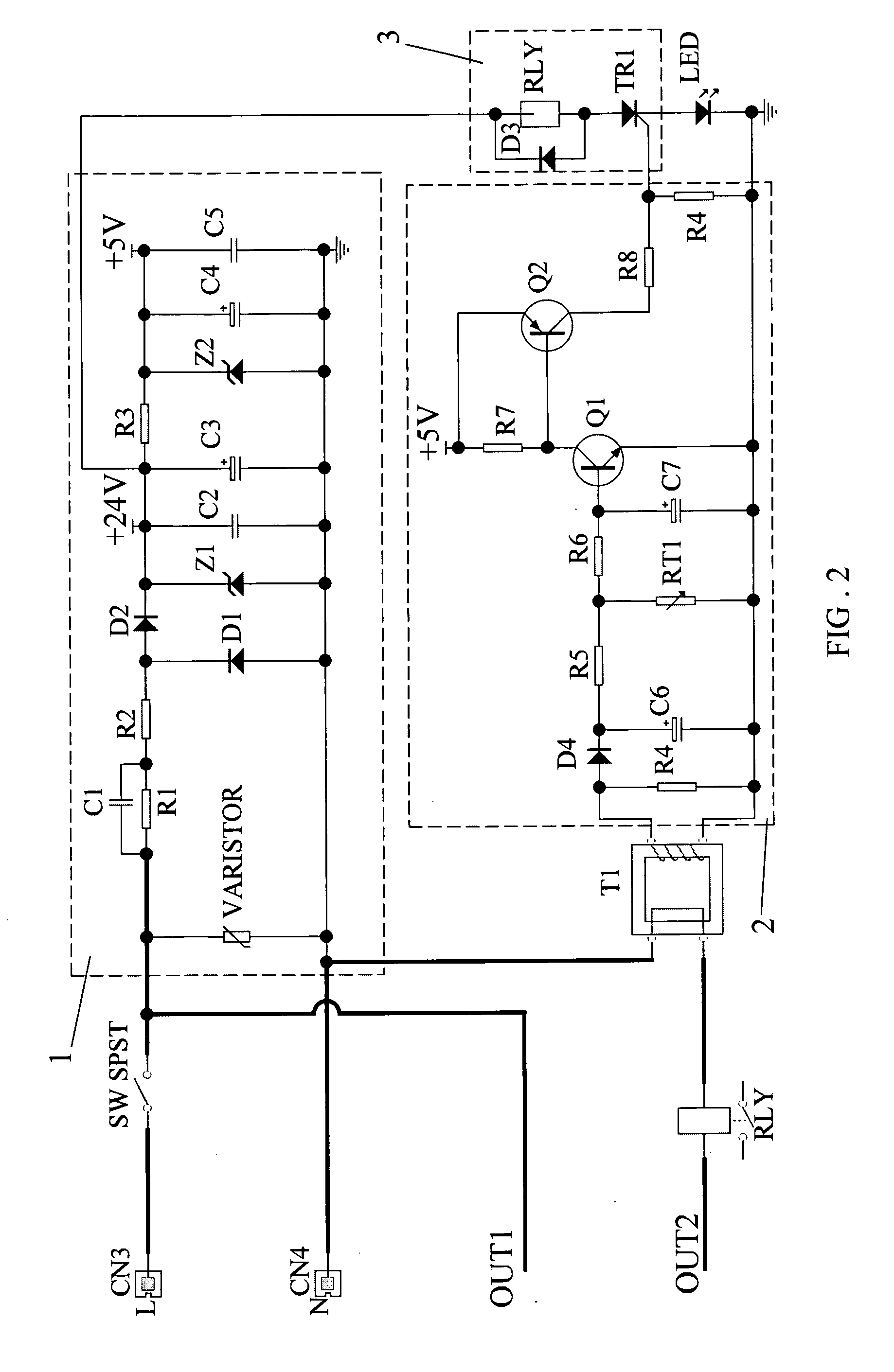
[0021]As shown in FIG. 2, a second preferred embodiment of a light-adjusting and current-limiting control circuit in the present invention has the same components as the first embodiment does, except that the sampling circuit is a current transformer T1, which has its input connected at two ends of the resistor R4, one of its outputs passed through the control port of the relay to connect to the output port OUT2, and the other output connected to the input port CN4. Similar to a hearting inductor, the current of a load can induce the output of the current transformer T1 as a voltage signal that is to pass through the signal adjusting circuit 2 to control the Relay or to send to a chip processor U1 for detecting. The sampling circuit based on the current transformer T1 is better than that based on manganese-copper line.
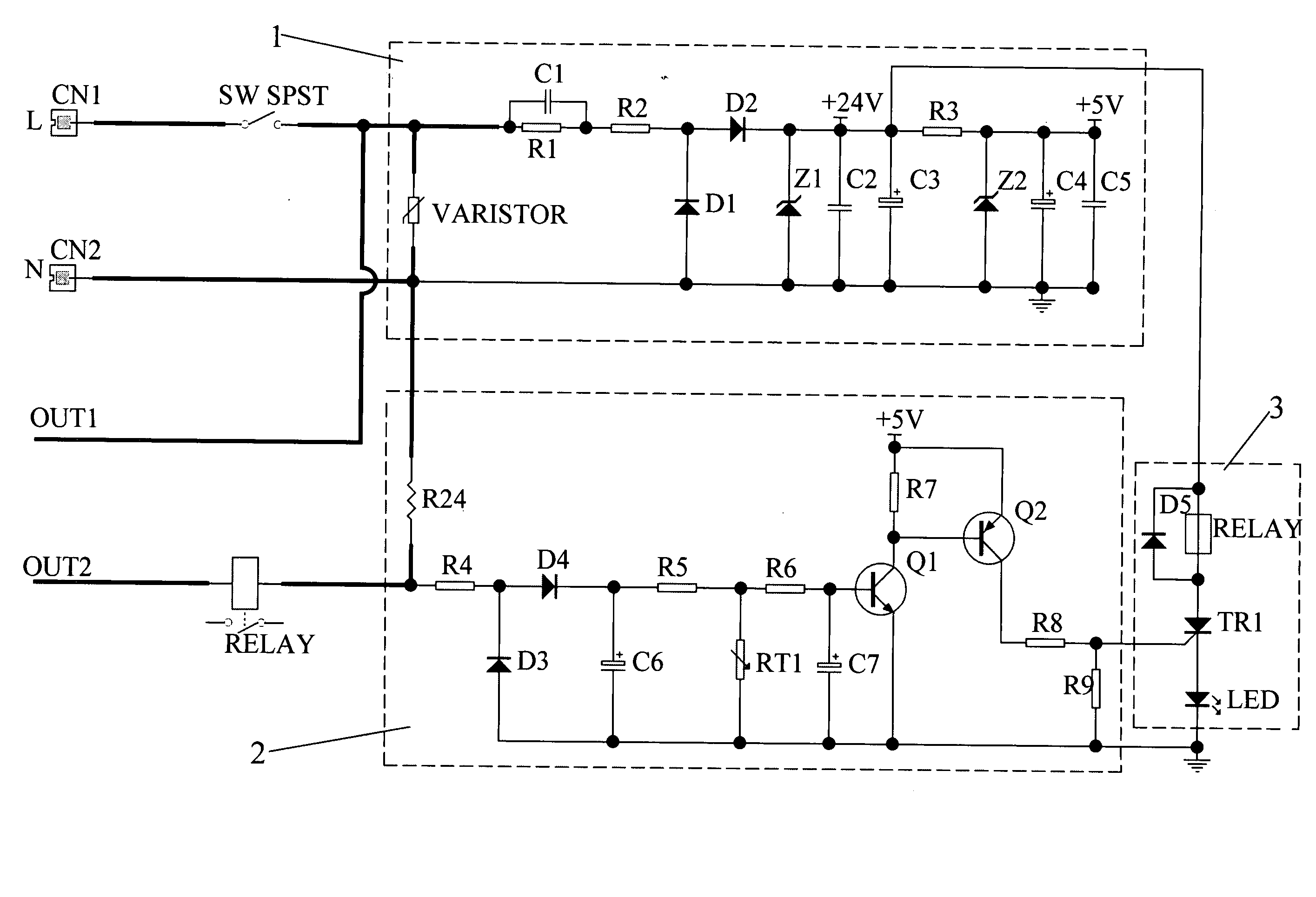
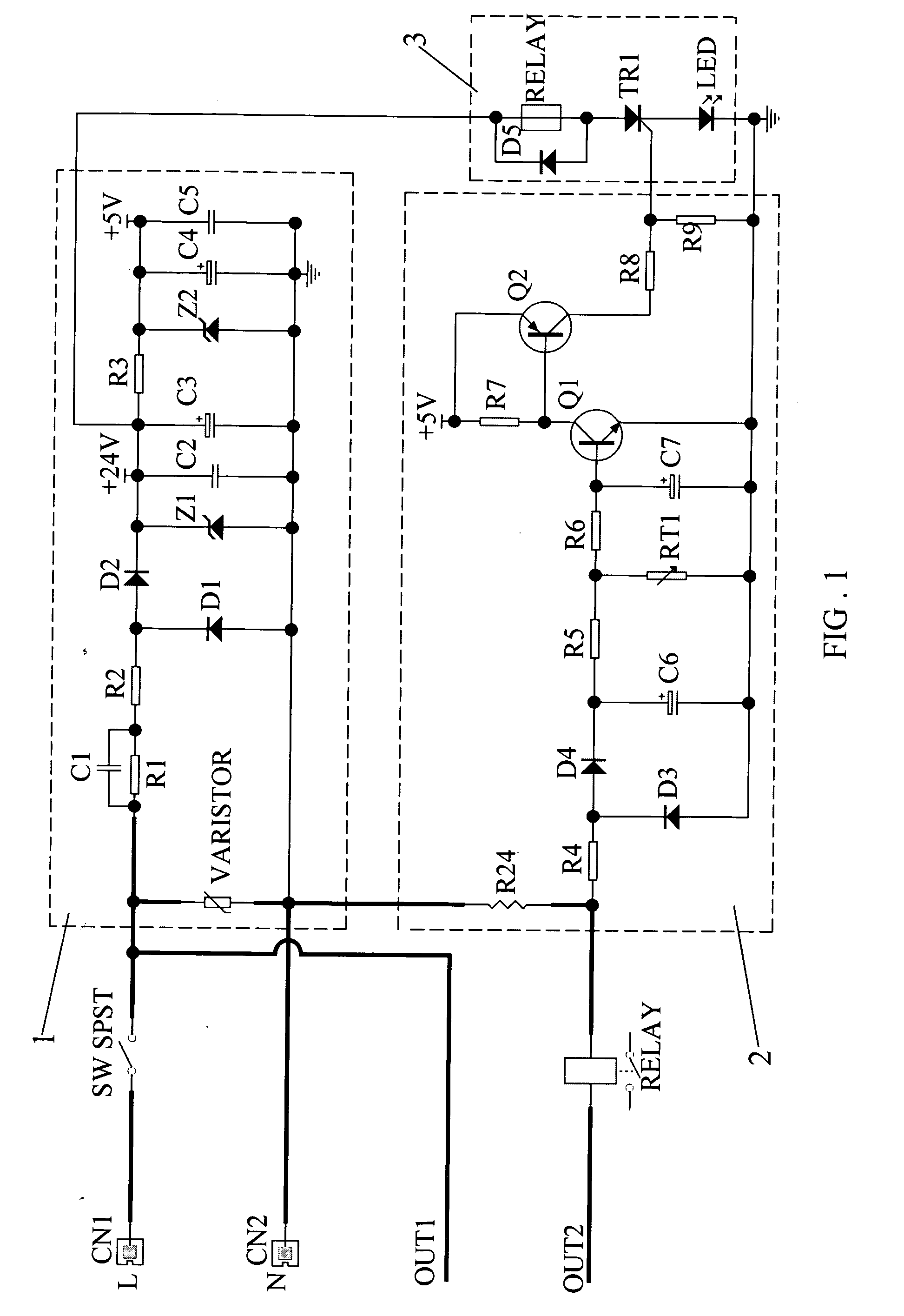
[0022]As shown in FIG. 1, a fourth feature of the preferred embodiment, is that the diode D3 has its negative pole connected to between the positive pole of the diode ...
fourth embodiment
[0032]Furthermore, as shown in FIGS. 3 and 4, a twelfth feature is that an LED indicating circuit 9 is as well included in the third and the present invention, composed of three light emitting diodes LED1, LED2 and LED3, and three resistors R19, R20 and R21. The LED1 has its negative pole connected to the ground, and its positive pole passed through the resistor R19 to connect to the PB2 pin (the 8th one) of the chip processor U1. The LED2 has its negative pole connected to the ground, and its positive pole passed through the resistor R20 to connect to the PB3 pin (the 9th one) of the chip processor U1. The LED3 has its negative pole connected to the ground, and its positive pole passed through the resistor R21 to connect to the PC3 pin (the 13th one) of the chip processor U1. In adjusting light, according to the brightness changing direction of the LEDs, a dynamic indication can be shown to tell the change of the brightness, from the bright to the dark or from the dark to the brigh...
PUM
 Abstract
Description
Claims
Application Information