Silicon controlled rectifier electrostatic discharge protection device for power supply lines with powerdown mode of operation

a technology of electrostatic discharge protection and silicon control, which is applied in the direction of semiconductor/solid-state device details, diodes, transistors, etc., can solve the problems of slow scr triggering, esd problem is particularly pronounced, and the product needs expensive repairs

Inactive Publication Date: 2005-07-07
SOFICS BVBA
View PDF9 Cites 48 Cited by
  • Summary
  • Abstract
  • Description
  • Claims
  • Application Information

AI Technical Summary

Problems solved by technology

During installation of integrated circuits into products, these electrostatic discharges may destroy the IC's and thus require expensive repairs on the products, which could have been avoided by providing a mechanism for dissipation of the electrostatic discharge to which the IC may have been subjected.
The ESD problem has been especially pronounced in complementary metal oxide semiconductor (CMOS) field effect transistors.
The N+ region diffusion 110, which is inserted as an integrated trigger means, is disadvantageous due to the excessive base widths of the NPN transistor T1131 and the PNP transistor T2132.
Therefore, the large lateral T1 and T2 transistor dimensions, due to the insertion of the N+ diffusion and the high recombination of charge carriers, results in slow SCR triggering.
Although the NMOS-based ESD protection device 908 of FIG. 9B is power down compliant, the NMOS device 908 has poor ESD voltage clamping characteristics.
Furthermore, the NMOS ESD protection device 908 is not area-efficient, and therefore encumbers manufacturing techniques that attempt to further reduce the size of the ICs.

Method used


Image

  • Silicon controlled rectifier electrostatic discharge protection device for power supply lines with powerdown mode of operation
  • Silicon controlled rectifier electrostatic discharge protection device for power supply lines with powerdown mode of operation
  • Silicon controlled rectifier electrostatic discharge protection device for power supply lines with powerdown mode of operation

Examples


second embodiment

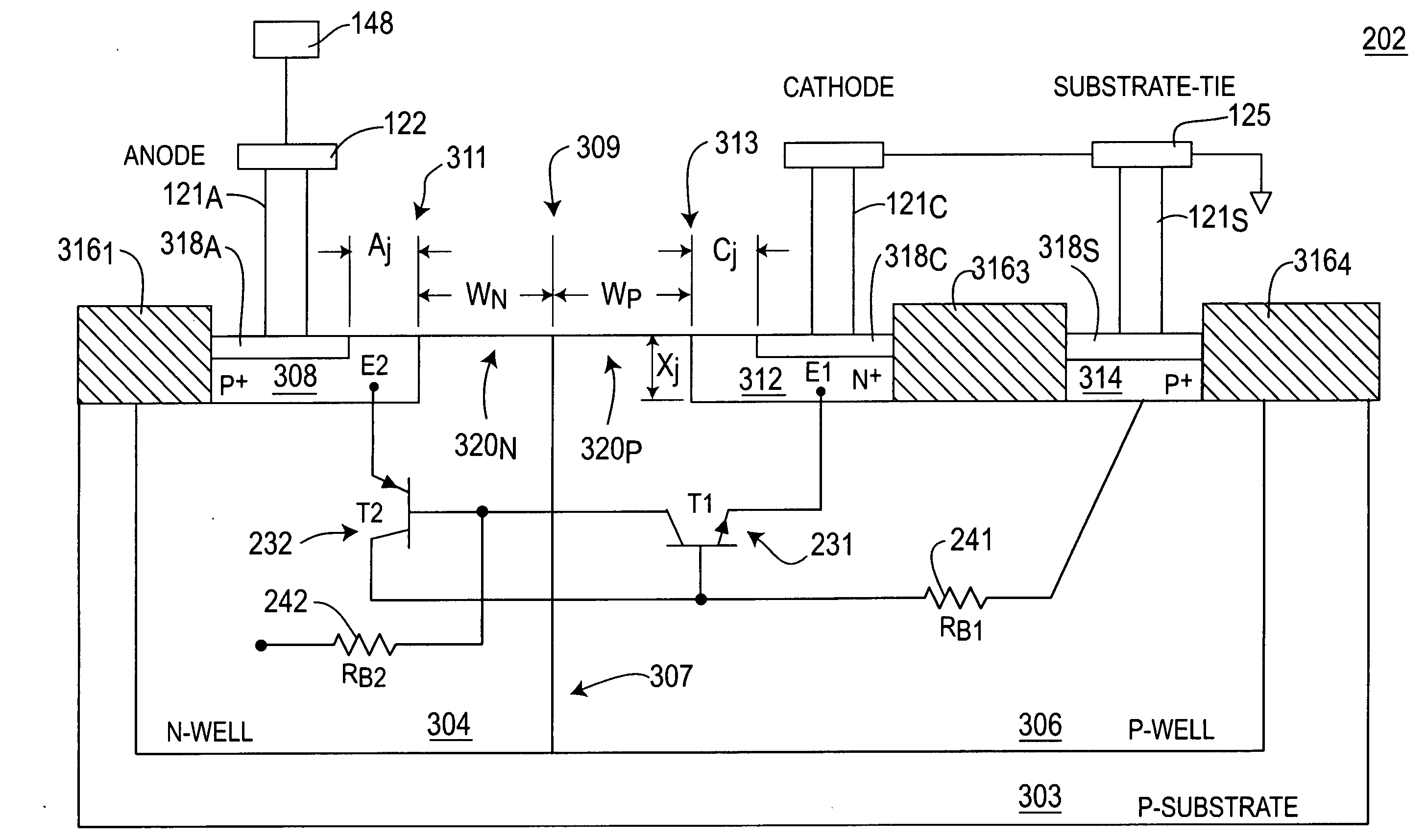
[0083]FIG. 6 depicts a cross-sectional view of a SCR 602 of the NMOS-triggered SCR ESD protection device 201. Specifically, FIG. 6 represents an SCR 202 that is fully silicided over the P+ and N+ regions 308 and 312. The base widths WN and WP of the transistors T2232 and T1231 are shown, respectively. Furthermore, shallow trench isolation (STI) is disposed over the entire SCR 202 as shown by STI regions 3161, 616, 3163, and 3164. In particular, the STI region 616 is disposed on the surface area 309 between the silicided layers 618A and 618C. Accordingly, the STI region 616 serves as an isolator between the anode 122 and cathode 124 to prevent shorting between the respective silicide layers 618A and 618C.

[0084] Moreover, the respective base widths WN and WP of the transistors T2232 and T1231 are determined by the length of the STI region 616. In particular, during manufacturing of the IC 200, the STI material is selectively deposited over the SCR 202. Thereafter, the P+ and N+ doped ...

first embodiment

[0095]FIG. 10 depicts a schematic diagram of an SCR ESD protection device 1000 of the present invention having two NMOS trigger devices 10201 and 10202 (collectively NMOS trigger devices 1020). In particular, the ESD protection device 1000 comprises a first SCR 10021 having a trigger NMOS device 10201, and a second SCR 10022 having an NMOS trigger device 10202, where both SCR's 10021 and 10022 (collectively SCRs 1002) are coupled between a first power line 10501 and a second power line 10502. The first SCR device 10021 is represented by a PNP transistor 10041 and an NPN transistor 10061. Similarly, the second SCR device 10022 is represented by a PNP transistor 10042 and an NPN transistor 10062, and both SCRs 1002 are configured in a conventional manner as discussed above with the respect to FIGS. 2A and 2B.

[0096] In particular, the emitter of the NPN transistor 10061 forms the cathode of the SCR 10021, the collector of the NPN transistor 10061 is coupled to the base of the PNP trans...

third embodiment

[0121]FIG. 12 depicts a schematic diagram of an SCR ESD protection device 1200 of the present invention having a diode trigger device 1202. FIG.12 is the same as FIG. 10 except that each NMOS trigger device 1020 is replaced by one or more serially coupled trigger diodes 1202.

[0122] For example, three exemplary diodes are serially coupled in a forward conduction direction from the emitter (anode) of the PNP transistor 10041 to the first gate G110081 of the first SCR 10021. Similarly, three exemplary diodes are illustratively serially coupled in a forward conduction direction from the emitter (anode) of the PNP transistor 10042 to the first gate G110082 of the second SCR 10022. Thus, both SCR's 1002 are triggered by the serially coupled diodes 1202.

[0123] Further, with respect to the third embodiment of FIG. 12, the N-wells of the two anti-parallel SCRs 1002 may be left floating or may be connected to a corresponding anode for each SCR to control the trigger and holding currents, or ...


PUM


Abstract

An electrostatic discharge (ESD) protection circuit in a semiconductor integrated circuit (IC) having protected circuitry. The ESD protection circuit includes a silicon controlled rectifier (SCR) having at least one first type high dopant region coupled to a first reference potential of the protected circuitry, and at least one second type high dopant region coupled to a second reference potential of the IC. The SCR is triggered by an external on-chip trigger device, which is adapted for injecting a trigger current into at least one gate of the SCR.

Description

CROSS REFERENCES [0001] This patent application claims the benefit of U.S. patent application Ser. No. 10 / 648,545, filed on Aug. 25, 2003, which claims the benefit of co-pending U.S. Provisional Application, Ser. No. 60 / 461,676, filed on Apr. 10, 2003, and U.S. patent application Ser. No. 10 / 007,833, filed on Nov. 5, 2001 (now U.S. Pat. No. 6,791,122), which also claims the benefit of U.S. Provisional Applications Ser. Nos. 60 / 280,345, filed Mar. 30, 2001; 60 / 246,123, filed Nov. 6, 2000; and 60 / 266,171, filed Feb. 2, 2001. This patent application is also related to commonly assigned and co-pending U.S. patent applications Ser. No. 10 / 783,844, filed Feb. 20, 2004, and Ser. No. 10 / 899,383, filed Jul. 26, 2004, as well as U.S. Pat. Nos. 6,768, 616 and 6,803,633. The aforementioned patent applications and patents are all incorporated by reference herein in their entireties.FIELD OF THE INVENTION [0002] This invention generally relates to the field of electrostatic discharge (ESD) protec...

Claims


Application Information

Patent Timeline
Patent Type & Authority Applications(United States)
IPC IPC(8): H01L27/02H01L29/74
CPCH01L29/87H01L27/0262
Inventor RUSS, CORNELIUS CHRISTIANMERGENS, MARKUS PAUL JOSEFARMER, JOHNVERHAEGE, KOEN GERARD MARIA
Owner SOFICS BVBA
Why Eureka
Try Eureka