Condensate and lint separator within a gaseous fluid exhaust system of a clothes dryer

a technology of condensate and lint separator, which is applied in the direction of clothes dryers, washing apparatus, textiles and paper, etc., can solve the problems of blockage of the dryer vent, the inability of the clothes dryer to filter 100% of the lint produced, and the prior art does not address the problem, so as to achieve a higher degree of fire safety, more efficient utility room combinations, and greater leeway

Active Publication Date: 2021-04-13
BAILEY WAYNE EDWARD
View PDF10 Cites 4 Cited by
  • Summary
  • Abstract
  • Description
  • Claims
  • Application Information

AI Technical Summary

Benefits of technology

[0096]This invention has particular application to homes and other dwellings allowing architects, builders and contractors greater leeway in designing more efficient utility room combinations. Clothes dryers may be positioned for best use of floor space while providing a higher degree of fire safety within the homes.

Problems solved by technology

Prior art does not address the problem of falling condensate and excess lint from a clothes dryer within a gaseous fluid exhaust system and their separate disposal.
Generally, clothes dryers do not filter 100% of the lint particulate produced during a typical drying cycle.
Additionally, the condensate can mix with the lint particulate creating a slurry like blend which can cause blockage in the dryer vent.
A blockage in the dryer vent can cause the dryer to underperform or over heat and possibly cause a fire.
Additionally, the Tignanelli invention does not address separation of falling condensate from dryer produced lint within a clothes dryer vent system and the separate disposal of each.
Additionally, the Doty invention does not address separation of falling condensate from dryer produced lint within a clothes dryer vent system and the separate disposal of each.
Additionally, the Shames invention does not address separating falling condensate from incoming lint within a clothes dryer vent system and the separate disposal of each.
Additionally, the Braggins invention does not address separating falling condensate from incoming lint within a clothes dryer vent system and the separate disposal of each.
Additionally, the Schuette invention does not address separation of falling condensate from dryer produced lint within a clothes dryer vent system and the separate disposal of each.
Additionally, the Dittmer invention does not address separation of falling condensate from dryer produced lint within a clothes dryer vent system and the separate disposal of each.

Method used


Image

  • Condensate and lint separator within a gaseous fluid exhaust system of a clothes dryer
  • Condensate and lint separator within a gaseous fluid exhaust system of a clothes dryer
  • Condensate and lint separator within a gaseous fluid exhaust system of a clothes dryer

Examples


Embodiment Construction

[0225]Throughout the following specific details are set forth in order to provide a more thorough understanding to persons skilled in the art. However, well known elements may not have been shown or described in detail to avoid unnecessarily obscuring the disclosure. Accordingly, the description and drawings are to be regarded in an illustrative, rather than a restrictive sense.

[0226]The preferred embodiment of the invention is shown in FIGS. 1 thru 13.

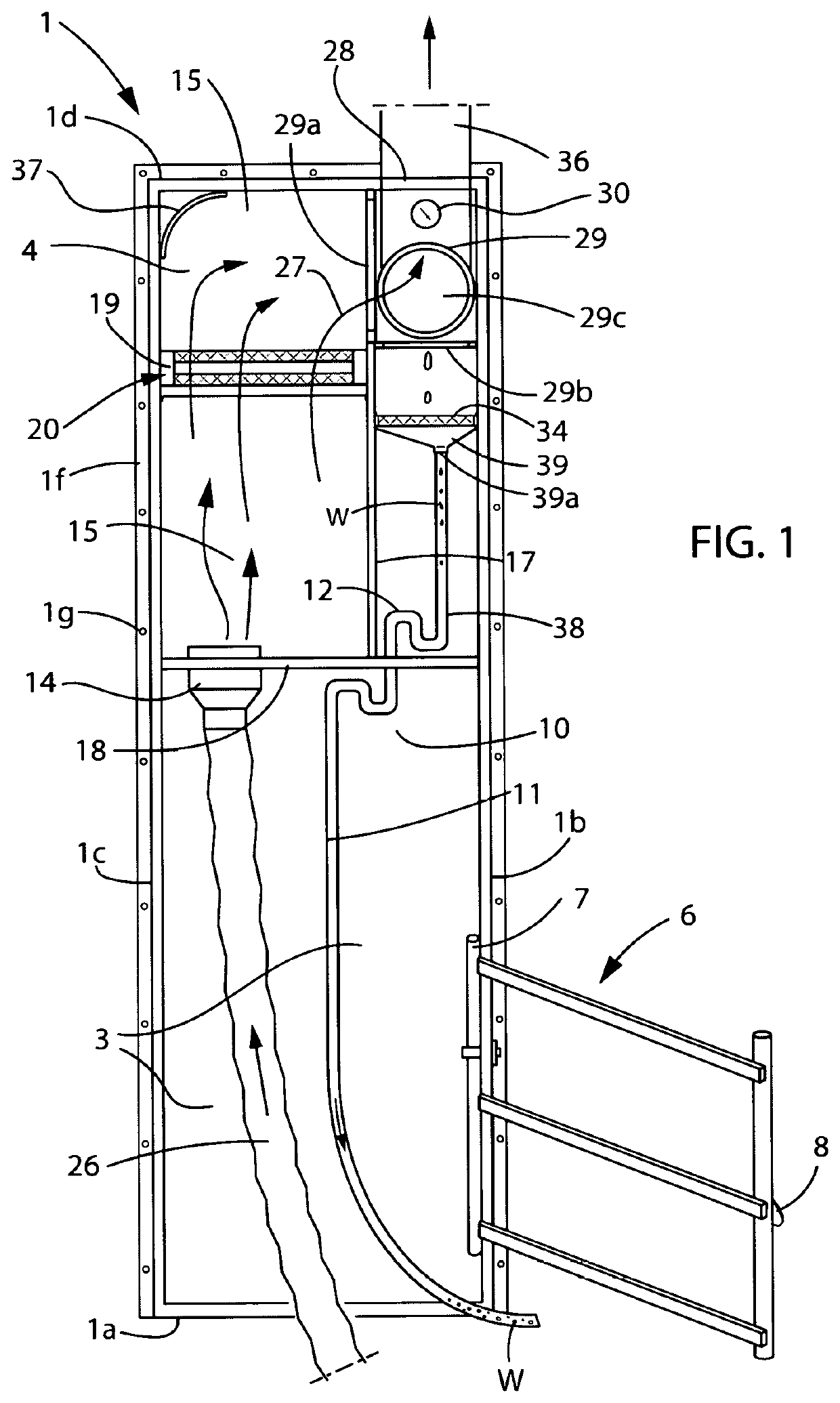
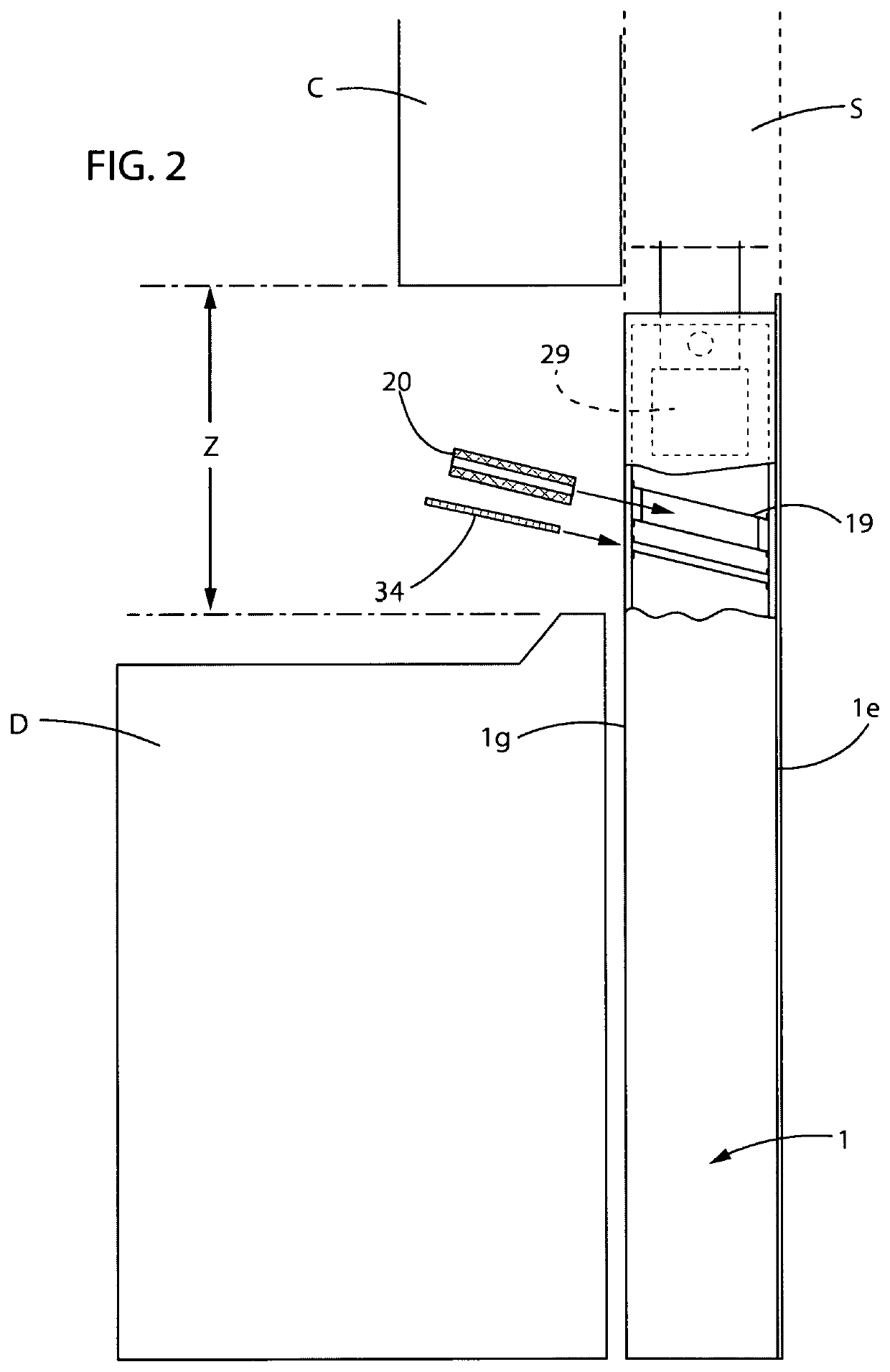
[0227]FIG. 1, depicts a front elevation view of the housing 1 within a gaseous fluid exhaust system, the housing 1 includes a bottom wall 1a as a floor, the housing 1 includes two side walls, right side wall 1b and left side 1c connected to the bottom wall 1a, the housing 1 has a top wall 1d connected to the side walls 1b and 1c, the housing 1 has a rear wall 1e, FIG. 2 connected to the bottom wall 1a, side walls 1b and 1c and the top wall 1d.

[0228]The bottom wall 1a, side walls 1b and 1c, rear wall 1e and top wall 1d provide structu...


PUM


Abstract

A housing as part of a clothes dryer's gaseous fluid exhaust system containing components for maintaining an open restriction-free airflow channel for maintaining the dryer's efficiency and sized to fit within a typical wall cavity of a building. A removable airflow filter for filtering and removing excess clothes lint, preventing entry of lint particulate into the upper exhaust vent pipe that may block exhaust airflow or blend with down falling condensate, which is generated from a clothes dryer's warm moist exhaust airflow. A diverter constructed to direct the exhaust airflow to a primary exterior location or to a secondary interior location. A condensate drain to separate falling condensate from exhaust airflow and dispose the condensate into an exclusive disposal system. The elements of this invention combine to secure the efficiency, longer life and safety of a clothes dryer and its exhaust system by removing lint particulate, separating exhaust airflow from falling condensate produced by a clothes dryer into the clothes dryer exhaust system.

Description

FIELD OF INVENTION[0001]The present invention relates to clothes dryer exhaust systems, and more particularly to filtering lint particulate from the clothes dryer's exhaust airflow and separating from falling condensate to prevent blending into a sludge.[0002]The airflow filter intercepts the lint particulate from the exhaust airflow before the exhaust airflow comes in contact with the falling condensate. By removing the lint particulate from the exhaust airflow before the airflow reaches the falling condensate, the risk of lint and condensate blending into a sludge is eliminated.[0003]After the lint has been filtered from the exhaust airflow, the clean exhaust airflow is directed past and separated from the falling condensate.[0004]The exhaust airflow is removed from the gaseous fluid exhaust system through one of the outlet ports.[0005]After separation, the airflow is directed out of the airflow exhaust system through a chosen outlet port and the condensate is directed out through...

Claims


Application Information

Patent Timeline
Patent Type & Authority Patents(United States)
IPC IPC(8): D06F58/22D06F58/24D06F58/20
CPCD06F58/22D06F58/20D06F58/24
Inventor BAILEY, WAYNE EDWARD
Owner BAILEY WAYNE EDWARD
Why Eureka
Try Eureka