Covering from mechanically interconnectable elements

a technology of mechanical interconnection and interconnection elements, which is applied in the direction of sheet joining, building components, fastening means, etc., can solve the problem of posing the risk of damage to the panel, and achieve the effect of locking with little and creating easily

Active Publication Date: 2014-06-17
SCHULTE GUIDO
View PDF22 Cites 19 Cited by
  • Summary
  • Abstract
  • Description
  • Claims
  • Application Information

AI Technical Summary

Benefits of technology

[0007]The invention is based on the object to provide a covering from mechanically inte

Problems solved by technology

This poses the risk of damage to the panels, even when working most carefully.
It is considered disadvantageous that a horizontal force first has to be exerted o

Method used


Image

  • Covering from mechanically interconnectable elements
  • Covering from mechanically interconnectable elements
  • Covering from mechanically interconnectable elements

Examples


Embodiment Construction

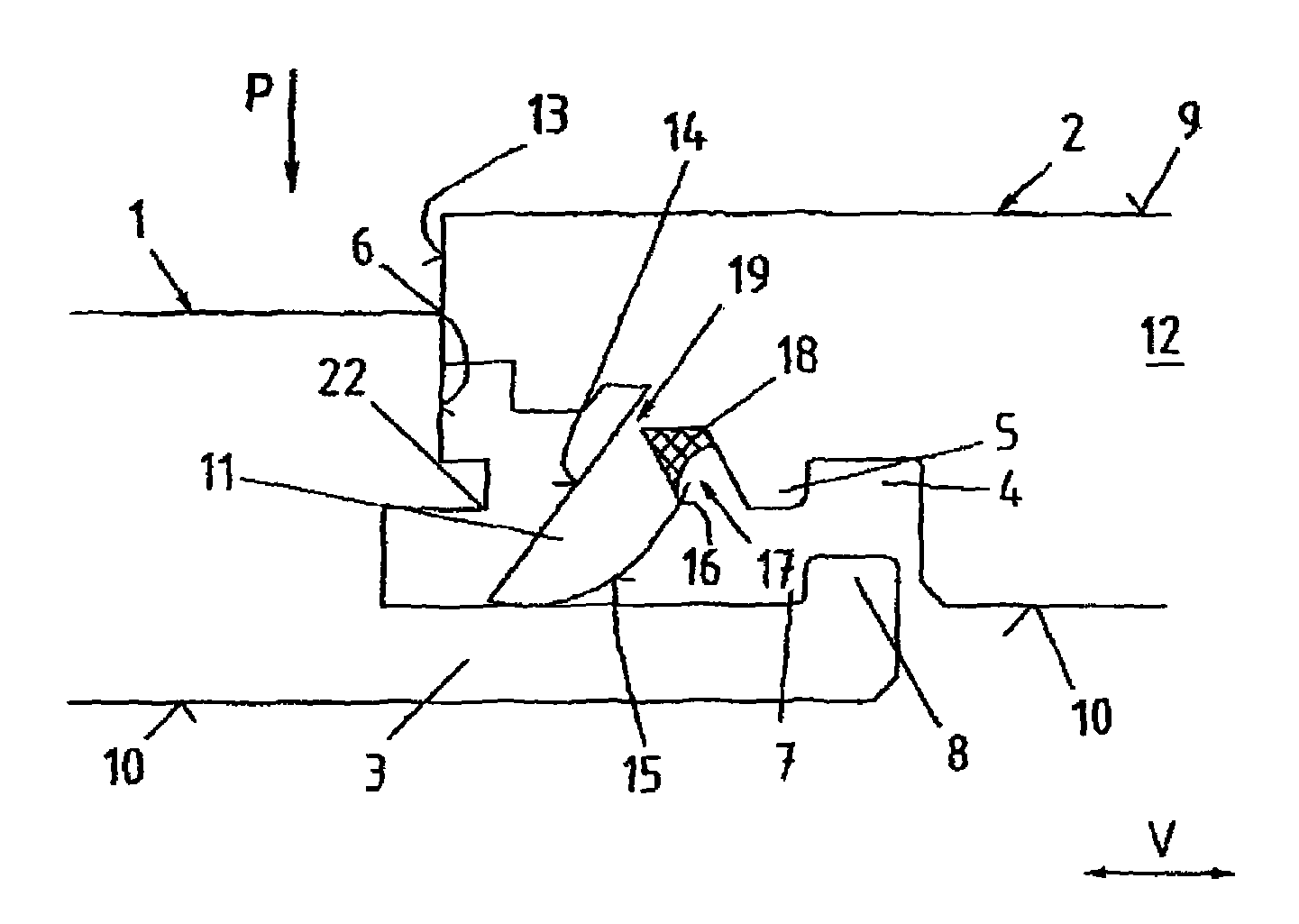
[0037]FIG. 1 shows a cross section through two elements 1, 2 in form of panels. This can be a head side cross section of the elements 1, 2. The elements 1, 2 are configured identical, so that the elements 1, 2 can be assembled to a floor covering.

[0038]FIG. 1 shows two neighboring elements 1, 2 before their locking. The representation shows a first element 1 in the image plane left and in the image plane right a second element 2, which is intended to be joined with the first element 1. The first element 1 has a locking rail 3 and the second element 2 a one sided coupling bulge 5 which is oriented downwards. The locking rail 3 of the first element 1 projects over a head side 6. The element 2 is arranged relative to the element 1, so that when lowering in the direction of the arrow P the coupling bulge 5 of the second panel engages in a coupling channel 7 of the locking rail 3 and the coupling channel 4 of the second element 2 engages with the coupling bulge 8 of the locking rail 3 of...


PUM

PropertyMeasurementUnit
Structureaaaaaaaaaa
Tensile propertiesaaaaaaaaaa
Elasticityaaaaaaaaaa

Abstract

A covering from mechanically interconnectable elements, wherein at least one of the elements is a panel, wherein the elements have on their confronting sides a complementary profiling and can be locked together via said profiling. The locking is caused by at least one tongue element which is connected to one of the elements in an articulated manner and which can be pivoted during the joining motion behind a locking edge of the adjacent element, said locking edge extending essentially in the horizontal direction. The tongue element is in part connected to a core of the element by means of an elastic material and is a one-piece component of the element prior to the joining motion, wherein the one-piece connection between the tongue element and the element is configured as a predetermined breaking site which is provided to fail, in particular break, when the tongue element is pivoted.

Description

CROSS-REFERENCES TO RELATED APPLICATIONS[0001]This application is the U.S. National Stage of International Application No. PCT / DE2010 / 001089, filed Sep. 15, 2010, which designated the United States and has been published as international Publication No. WO 2011 / 038709 A1 and which claims the priority of German Patent Application, Serial No. 10 2009 048 850.1, filed Oct. 2, 2009, pursuant to 35 U.S.C. 119(a)-(d).BACKGROUND OF THE INVENTION[0002]The invention relates to a covering from mechanically interconnectable elements.[0003]Wall, ceiling, and floor coverings, such as for example prefabricated parquet, real wood floors or laminate floorings, are made of several rows of predominantly rectangular panels. Conventionally, the panels have continuous grooves on a longitudinal side and a head side, and on the respective opposing longitudinal side or head side, respectively, continuous tongues which form fittingly match the grooves. The panels are installed by joining the groove and tong...

Claims


Application Information

Patent Timeline
IPC IPC(8): E04B2/00
CPCE04F2201/041E04F15/02405F16B5/0076E04F2201/0161E04F2201/0176E04F2201/0169E04F2201/0153E04F15/02E04F2201/0146E04F2201/049E04F2201/0138E04F13/08
Inventor SCHULTE, GUIDO
Owner SCHULTE GUIDO
Why Eureka
Try Eureka