Variable identification stamp

Inactive Publication Date: 2012-05-24
OPTIZ
3 Cites 7 Cited by

AI-Extracted Technical Summary

Problems solved by technology

These documents do not teach any detent nose...

Method used

[0050]According to a further embodiment, the shape of locking groove and detent nose can be modified. For example, the V-shape of the locking groove can be combined with a semi-cylindrical shape of the detent nose, or locking groov...

Benefits of technology

[0022]Thus, contrary to the state of the art of documents DE 93 14 975 U1 and DE 197 30 772 A1 described at the outset, the working pressure acts in the locking direction and the detent nose and the locking groove (without any components additionally to be mounted) a...

Abstract

An identification stamp comprises a housing (1, 2) having a transferrable marking (11) at the housing end face and an adjustment element (3) which is inserted in the housing (1, 2) in an adjustable manner and which is provided with a transferrable marking (31) at its end face. When the adjustment element (3) is adjusted with respect to the housing (1, 2), the marking (11) is adjusted relative to the marking (31). An engagement means (33, 13) is made of at least one detent nose (33), which is integrally arranged on the adjustment element (3) in the axial direction in a protruding manner and which engages with one of a plurality of locking grooves (13) integrally arranged on the housing (1) in the axial direction in a recessed manner.

Application Domain

Moulding toolsStamping

Technology Topic

EngineeringMechanical engineering

Image

  • Variable identification stamp
  • Variable identification stamp
  • Variable identification stamp

Examples

  • Experimental program(1)

Example

[0027]In the following, the embodiments of the present invention are described.
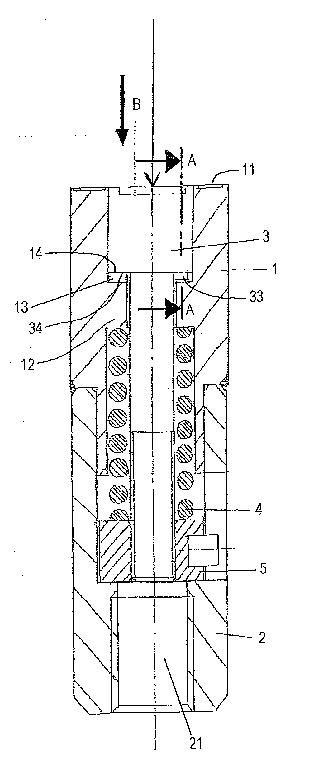
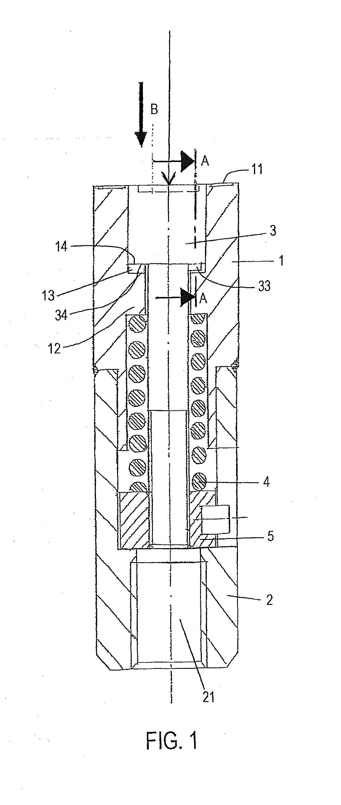
[0028]FIG. 1 shows a view in the longitudinal section of an identification stamp according to the invention.
[0029]In the description of the present invention, the upper side of the identification stamp is defined as the side comprising the marking which is to be applied onto the workpiece to be marked. The lower side of the identification stamp is defined as the side that faces away from the marking side and is used for mounting on an embossing tool. Therefore, in FIG. 1, the marking side is at the top.
[0030]The identification stamp according to the invention is composed of an upper part 1 of the housing body (hereinafter: housing body upper part 1) and a lower part 2 of the housing body (hereinafter: housing body lower part 2). The upper side (upper surface) of the housing body upper part 1 forms the embossing side (marking side). The housing body upper part is formed as a cylinder and is provided with a through hole. The upper surface (end face) of the cylinder (of the cylinder wall) is provided with a marking area 11 which, in the operation of the identification stamp, faces the product to be processed, which is to be marked (plastics, metal, etc.). In the present embodiment, the marking area 11 is provided with the numerals from 1 to 8, as this is shown in FIG. 2 and FIG. 3. Thus, the marking area 11 is located at the end face or upper end face of the base body upper part 1.
[0031]The through hole in the housing body upper part 1 is provided with a projection on the housing (housing projection) 12 projecting towards the imaginary central axis of the housing body upper part 1 at the whole inner circumferential surface of the through hole.
[0032]In the present embodiment, the housing projection 12 is elaborated as a flange which is rectangular in the longitudinal section (of FIG. 1) and which is located slightly above the center in the axial direction of the base body upper part 1. The surface of the housing projection 12 pointing upwards forms a contact surface 14.
[0033]The downwardly directed surface of said housing projection 12 also forms a contact surface (without reference signs).
[0034]In the lower area of the base body upper part 1, a step of a suitable length is elaborated to allow assembling with a housing body lower part 2. Therefore, in the present embodiment, a connecting area is provided on the outer circumference of the housing body lower part 1 such that the lower end area has a smaller outer diameter than the upper area of the housing body upper part 1. In said area having a smaller outer diameter of the housing body upper part 1, a thread for establishing a connection with the housing body lower part 2 is elaborated.
[0035]The housing body lower part 2 is also formed as an elongate cylinder provided with a through hole. At the lower side of the housing body lower part 2, the through hole is enlarged into a screw-in hole 21 which is provided with an internal thread and is used for being screwed into a respective embossing tool or marking tool. Slightly above the threaded area of the screw-in hole 21, the inner diameter of the through hole is enlarged and has a dimension adapted for receiving the lower section of the housing body upper part 1. Therefore, the upper section of the inner circumferential side of the through hole in the housing body lower part 2 is provided with an internal thread which is in a threaded engagement with the outer thread of the lower section of the housing body upper part 1. Thus, the upper section of the housing body lower part 2 and the lower section of the housing body upper part 1 overlap in the radial direction.
[0036]The identification stamp of the present invention further has a rotatable adjustment element 3, a spring element 4 and a spring stroke adjusting element 5. When screwed together, the housing body upper part 1 and the housing body lower part 2 form a spring chamber along the through hole between the lower contact surface of the housing projection 12 and the step in the housing body lower part 2, which also serves as contact surface, located above the screw-in hole 21 and forming the diameter extension in the through hole of the housing body lower part 2. The spring element 4 and the spring stroke adjusting element 5 are accommodated in this spring chamber in the manner shown in FIG. 1.
[0037]Therein, the spring stroke adjusting element 5, which is formed as a nut having a central through hole, is accommodated in the lower section adjacent to the contact surface located above the screw-in hole 21. An internal thread is elaborated in said central through hole. The spring element 4 is accommodated in a suitably biased state between the upper surface of the spring stroke adjusting element 5 and the lower contact surface of the housing projection 12.
[0038]The adjustment element 3 is a cylindrical body having a head at its upper side and an elongate cylindrical section having a smaller outer diameter than on the head at the bottom side. The head has an outer diameter which is dimensioned such that it can be inserted into the upper section of the housing body upper part 1 from the top, wherein the inner circumferential surface of the upper section of the housing body upper part 1 serves as guiding surface for the outer surface of the head of the adjustment element 3. Thus, the head of the adjustment element 3 can be inserted into the upper area of the housing body upper part up to the upper contact surface 14 of the housing projection 12. At the upper surface or end face, the head of the adjustment element 3 is provided with a marking area 31, as shown in FIG. 2, having an adjustment groove 32 into which an adjusting tool (e.g. an adjusting tool in the form of a screw driver) can be inserted. The adjustment groove 32 is elaborated as an arrow pointing to one of the numerals of the marking area 11 of the housing body upper part 1, i.e. in the present embodiment to one of numerals 1 to 8. Moreover, if required, the marking area 31 may comprise further symbols, as is shown in FIG. 2.
[0039]The diameter of the lower elongate cylinder piece of the adjustment element 3 is smaller than the outer diameter of the head. Thus, a step is formed at the connecting point between the elongate cylinder piece and the head.
[0040]At this step, the lower surface of the head of the adjustment element 3 forms a contact surface 34 which is in abutment with the contact surface 14 of the housing body upper part 1. The adjustment element 3 is rotatable relative to the housing body, this rotational movement being effected by an adjusting tool inserted into the adjustment groove 32 of the adjustment element 3. The elongate cylinder provided on the head of the adjustment element 3 and forming an elongation pointing downwards has an outer diameter which is smaller than the inner circumferential surface of the housing projection 12 and the spring element 4. The lower section of said cylinder is provided with a thread being in threaded engagement with the inner thread of the spring stroke adjusting element 5. The spring stroke adjusting element 5 can be screwed along said elongate cylinder of the adjustment element 3 in order to adjust the spring stroke of the spring element 4 and, thus, the biasing thereof.
[0041]The adjustment element 3 can, thus, be inserted into the through hole of the housing body upper part 1 and the housing body lower part 2 at the top (marking side) until the contact surfaces 14 and 34 abut against each other. In this way, the operating state is reached. In this operating state, the marking areas 11 and 31 forming the marking surfaces are substantially aligned with each other.
[0042]The contact surfaces 14 and 34 are not completely flat. The head of the adjustment element has a detent nose 33 which is formed as a projection protruding downwards, i.e. in the axial direction, at its lower contact surface 34 in the area which is in abutment with the upper contact surface 14 of the projection 12. In the present embodiment, the detent nose 33 is formed in a V-shape having a flattened end, as this is shown in FIG. 1 and in the sectional view A-A in FIG. 4. The contact surface 14 on the housing projection 12 is provided with a plurality of locking grooves 13 which are recessed in the axial direction of the identification stamp and in which the detent nose 33 can lock in place. In the present embodiment, eight locking grooves 13 are provided on the contact surface 14 at equal distances, said locking grooves corresponding to the adjustment possibilities represented by the eight numerals in the marking area 11. Each locking groove 13 is elaborated such that the detent nose 33 engages such that the contact surfaces 14 and 34 abut against each other flatly. Therefore, in the present embodiment, the locking groove 13 is formed as a V-shaped recess, as this is clearly shown in FIG. 4.
[0043]Ideally, the detent nose 33 and the locking grooves 13 extend in a radial direction. The locking grooves 13 are preferably shaped such that they reach up to the inner circumference of the upper region of the housing body upper part 1. The detent nose 33 is preferably shaped such that it leaves an inteimmediate space to the inner circumference of the upper area of the housing body upper part 1, as this is shown in FIG. 1.
ADVANTAGES OF THE EMBODIMENT
[0044]For realizing the locking function, the identification stamp described in the above embodiment comprises the housing element 1 and the adjustment element 3 on which the detent nose 33 and the locking grooves 13 are integrally arranged, respectively. Thus, the identification stamp comprises a minimum number of components.
[0045]This construction makes it possible to realize small locking depths, small locking distances and, thus, small constructional dimensions.
[0046]As, in operation, the embossing pressure on the adjustment element 3 acts in the same direction in which the detent nose 33 is pressed into the locking groove 13, the identification stamp according to the invention is very safe to operate.
Further Embodiments
[0047]A further embodiment describes the alternative of the detent nose not being provided on the adjustment element, but on the housing projection. Accordingly, the locking grooves are not provided on the housing projection, but on the adjustment element. This leads to a similar advantageous embodiment, which achieves similar effects.
[0048]In the afore-described embodiment, the marking area 11 is provided with numerals from 1 to 8 and, therefore, eight locking grooves 13 are provided accordingly. According to a further embodiment, numerals 1 to 12 and twelve locking grooves can be provided instead in the marking area, so that a locking adjustment with regard to the months is achieved. In a further embodiment, numerals 1 to 31 and thirty-one locking grooves can be provided in the marking area, allowing the setting of a day. Basically, any selection of numerals provided in the marking area is conceivable with the corresponding number of locking grooves. Moreover, also other symbols apart from numerals are embossable in the respective marking area. In this case, too, the marking area 11 comprises symbols the number of which corresponds to the number of locking grooves 13.
[0049]According to the afore-described embodiment, the detent nose 33 is formed into a V-shape having a flattened end, as this is shown in FIG. 4. According to a further embodiment, the detent nose can be made to have a rounded-off end, whereby the wear on the contact surface 14 of the projection 12 can be reduced.
[0050]According to a further embodiment, the shape of locking groove and detent nose can be modified. For example, the V-shape of the locking groove can be combined with a semi-cylindrical shape of the detent nose, or locking groove as well as detent nose can be semi-cylinders. In this case, too, the wear of the contact surface 14 can be reduced. Also further shapes are conceivable, provided that the locking function is realized in a sufficiently safe manner.
[0051]According to a further non-claimed example, not one detent nose, but several detent noses can be provided on the adjustment element. According to the non-claimed example, two detent noses can be formed so as to be diagonally opposite on the lower side of the adjustment element. In this way, the force distribution is optimized during the adjusting procedure (locking adjustment), and e.g. a slanted position of the adjustment element is avoided. According to a further non-claimed example, the provision of several detent noses is also applicable with the alternative, according to which the detent nose is not provided on the adjustment element, but on the housing projection.
[0052]Although this invention has been shown and described with respect to the detailed embodiments thereof, it will be understood by those skilled in the art that various changes in form and detail thereof may be made without departing from the spirit and the scope of the invention.

PUM

PropertyMeasurementUnit
Circumference

Description & Claims & Application Information

We can also present the details of the Description, Claims and Application information to help users get a comprehensive understanding of the technical details of the patent, such as background art, summary of invention, brief description of drawings, description of embodiments, and other original content. On the other hand, users can also determine the specific scope of protection of the technology through the list of claims; as well as understand the changes in the life cycle of the technology with the presentation of the patent timeline. Login to view more.

Similar technology patents

Emergency alarm system for restricted spaces

ActiveUS11127276B2economical to manufactureeasily instal and replace
Owner:PROKES JAMES MICHAEL

Lantern stand

ActiveUS20150226411A1economical to manufacturedurable in use
Owner:NOONAN JOHN F

Sorting device for coin tester

InactiveUS20060037836A1economical to manufacturereliable function
Owner:WALTER HANKE MECHANISCHE WERKSTATTEN

Power generating system for a rotatory dental apparatus

PendingUS20220104919A1economical to manufacture
Owner:AEROBINE INC

Running shoe

ActiveUS20210219654A1enhance athletic performanceeconomical to manufacture
Owner:RINALDI MASSIMO +2

Classification and recommendation of technical efficacy words

  • economical to manufacture

Audio distribution and production system

InactiveUS20020177914A1economical to manufactureeasy and flexible programmability
Owner:CHASE TIM

Folded tube for a heat exchanger and method of making same

InactiveUS20050092476A1economical to manufacture
Owner:VALEO INC

Suspension system for a row crop planter unit

ActiveUS7401561B1economical to manufacturedurable in use
Owner:KURZ CLARE D

Propellants and explosives with flouro-organic additives to improve energy release efficiency

InactiveUS6843868B1economical to manufacturewidespread , cost effective use
Owner:THE UNITED STATES OF AMERICA AS REPRESENTED BY THE SECRETARY OF THE NAVY

Low temperature formation of backside ohmic contacts for vertical devices

InactiveUS6909119B2economical to manufacture
Owner:WOLFSPEED INC
Why Eureka
Try Eureka