This helps you quickly interpret patents by identifying the three key elements:
Problems solved by technology
Method used
Benefits of technology
[0013]The electrode comprising the firing tip formed of the at least one perovskite structure and/or at least one spinel structure is economical to manufacture and provides a longer useful life, compared to other electrodes used in ignition devices. The combination of th
Problems solved by technology
These higher operating temperatures, however, are pushing electrodes of the spark plugs to the very limits of their material capabilities.
Since combustion environments are highly oxidizing, corrosive wear including deformation and fracture caused by high temperature oxidation and sulfidation can result and is particularly exacerbated at the highest operating temperatures.
), tensile, creep rupture and fatigue strength also have been observed to decrease significantly which can result in deformation, cracking and fracture of the electrodes.
Depending on the electrode design, specific operating conditions and other factors, these high temperature phenomena may contribute individually and collectively to undesirable corrosion and erosion of the electrode and diminished p
Method used
Image
Click on the blue label to locate the original text in one second.
Reading with bidirectional positioning of images and text.
Examples
Example
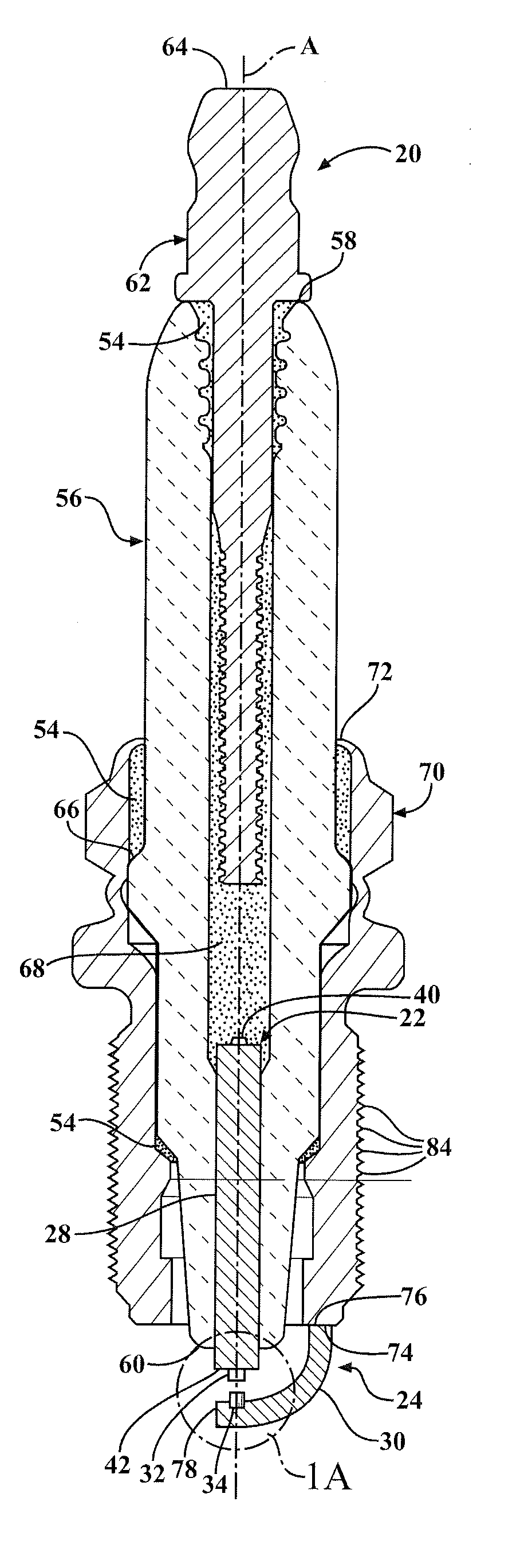
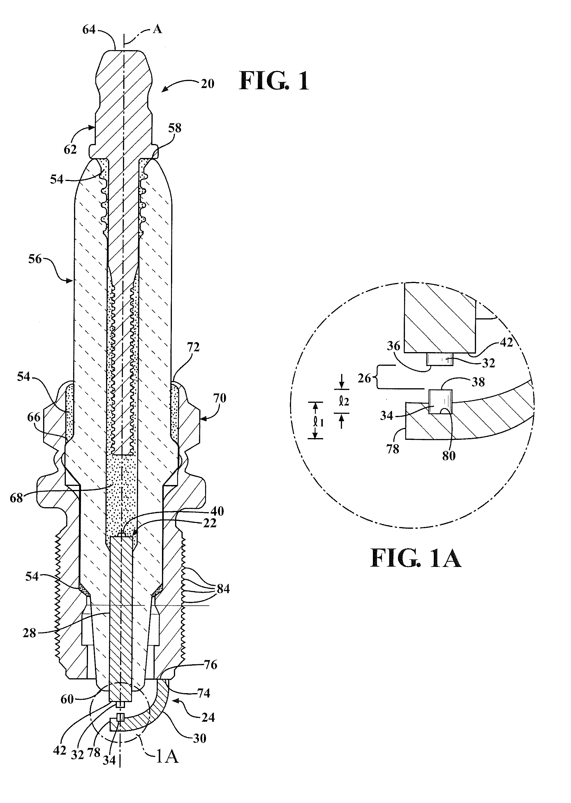
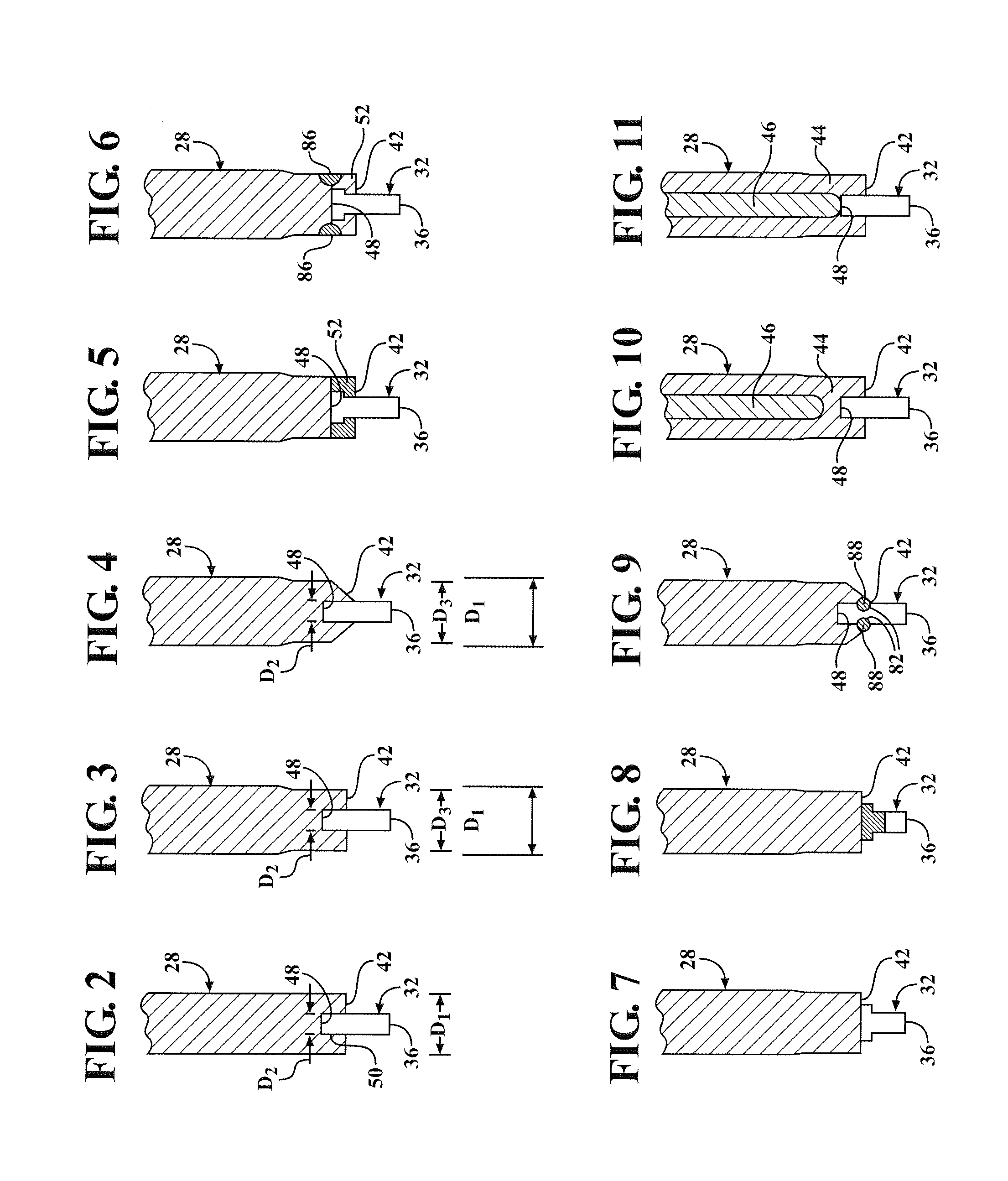
[0018]One aspect of the invention provides a spark plug 20 for igniting a mixture of fuel and air of an internal combustion engine. As shown in FIGS. 1 and 1A, the spark plug 20 includes a center electrode 22 and a ground electrode 24 providing a spark gap 26 therebetween. At least one of the electrodes 22, 24 includes a body portion 28, 30 formed of a thermally conducive material and a firing tip 32, 34 formed of a ceramic material disposed on the body portion 28, 30. The ceramic material of the firing tip 32, 34 provides a firing surface 36, 38 for emitting a spark to ignite the mixture of fuel and air.
[0019]By forming the firing tip 32, 34 of the ceramic material, a lower operating temperature is provided at the firing tip 32, 34. By forming the body portion 28, 30 of a thermally conductive material, heat is effectively conducted away from the ceramic firing tip 32, 34. Thus, the electrode 22, 24 of the present invention, with the thermally conductive body portion 28, 30 and the ...
PUM
Abstract
A spark plug (20) for igniting a mixture of fuel and air of an internal combustion engine comprises a center electrode (22) and a ground electrode (24). At least one of the electrodes (22, 24) includes a body portion (28, 30) formed of thermally conductive material and a firing tip (32, 34) disposed on the body portion (28, 30). The firing tip (32, 34) includes a ceramic material, providing an exposed firing surface (36, 38). The ceramic material is an electrically conductive, monolithic ceramic material. The ceramic material of the firing tip (32, 34) includes at least one perovskite structure and/or at least one a spinel structure.
Description
CROSS REFERENCE TO RELATED APPLICATIONS[0001]This application is a Continuation-in-Part and claims the benefit of U.S. patent application Ser. No. 14 / 085,293, filed Nov. 30, 2013, which is a Division and claims the benefit of U.S. patent application Ser. No. 13 / 279,418, filed Oct. 24, 2011, now U.S. Pat. No. 8,614,541, which is a Continuation-in-Part and claims the benefit of U.S. application Ser. No. 12 / 201,590, filed Aug. 29, 2008, now U.S. Pat. No. 8,044,565, which is a Continuation-in-Part and claims the benefit of U.S. patent application Ser. No. 12 / 200,244, filed Aug. 28, 2008, now U.S. Pat. No. 8,044,561, a the entire contents of which are hereby incorporated by reference in their entirety.BACKGROUND OF THE INVENTION[0002]1. Field of the Invention[0003]The invention relates generally to ignition devices for internal combustion engines, such as spark plugs, and more particularly to the electrodes therefore.[0004]2. Related Art[0005]Internal combustion engines include ignition ...
Claims
Application Information
Patent Timeline
Application Date:The date an application was filed.
Publication Date:The date a patent or application was officially published.
First Publication Date:The earliest publication date of a patent with the same application number.
Issue Date:Publication date of the patent grant document.
PCT Entry Date:The Entry date of PCT National Phase.
Estimated Expiry Date:The statutory expiry date of a patent right according to the Patent Law, and it is the longest term of protection that the patent right can achieve without the termination of the patent right due to other reasons(Term extension factor has been taken into account ).
Invalid Date:Actual expiry date is based on effective date or publication date of legal transaction data of invalid patent.