Air supply system with reduced oil passing in compressor

Inactive Publication Date: 2008-02-28
HALDEX BRAKE
View PDF11 Cites 4 Cited by
  • Summary
  • Abstract
  • Description
  • Claims
  • Application Information

AI Technical Summary

Benefits of technology

[0013]Accordingly, it is an object of the present invention to provide an air

Problems solved by technology

How to unload the air compressor to save horsepower when the compressor is not pumping, without having other problems occur, has been a long standing problem in the art.
This method of unloading is now generally viewed as unsatisfactory because of the noise produced, and the horsepower losses incurred.
In many cases, when the intake valve was held open on a single cylinder air compressor and the compressor was supplied with naturally aspirated air, which was common at the time, since the compressor intake was supplied with a separate air cleaner, pumping back and forth through the air cleaner in many cases destroyed the air cleaner, or reduced its efficiency so it would not perform for the purpose for which it was intended.
This caused some truck manufacturers to switch to a system supplied with turbocharged inlet air from the engine turbocharger to avoid the air cleaner problems and assure a clean inlet air supply, but it was then found that when unloading in the conventional way, by holding the intake valve open, the faster the engine was running, the denser the air, and the more horsepower was lost due to the unloading.
A clutched compressor was developed, but was not felt to be the answer to the hors

Method used


Image

  • Air supply system with reduced oil passing in compressor
  • Air supply system with reduced oil passing in compressor
  • Air supply system with reduced oil passing in compressor

Examples


Example

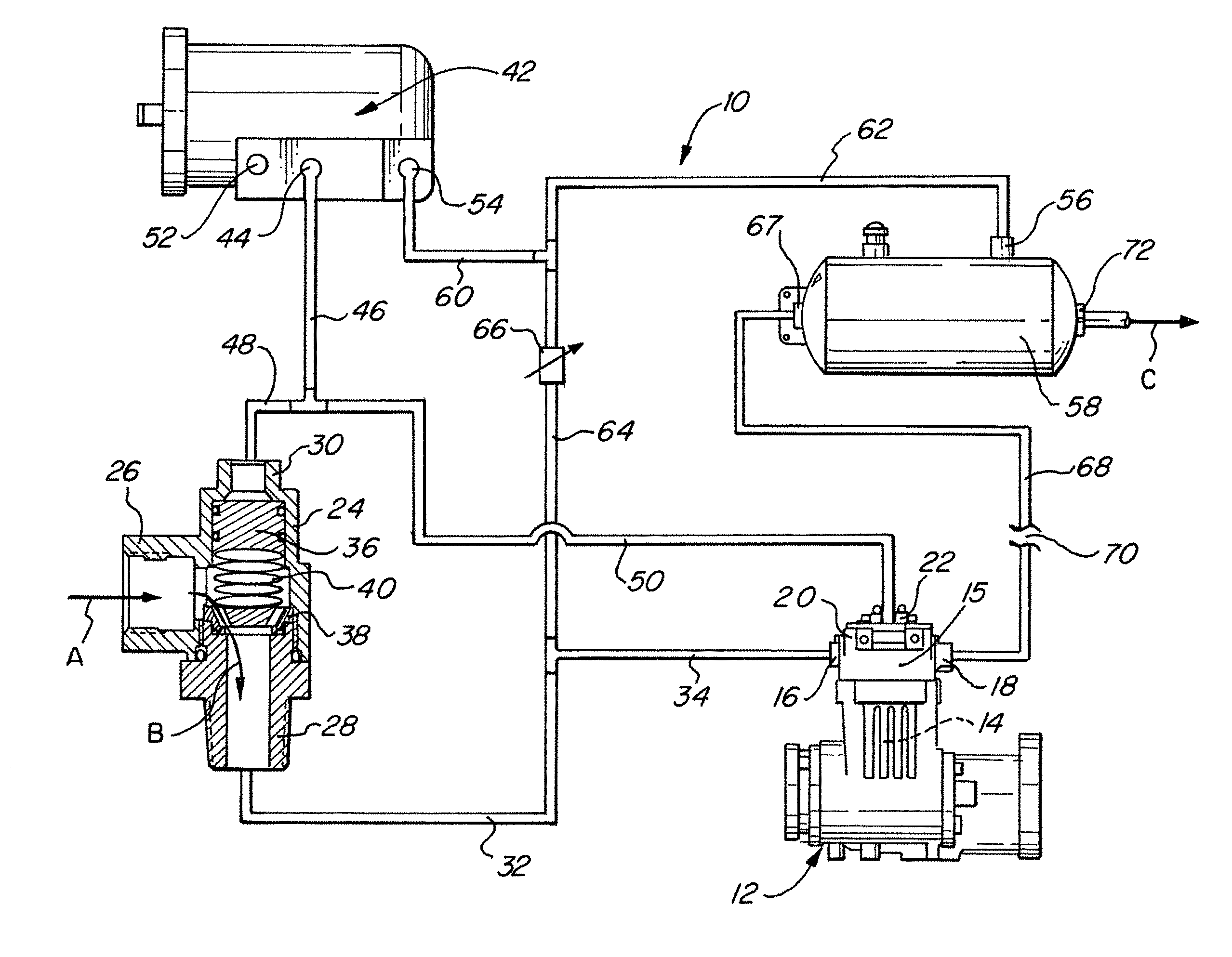
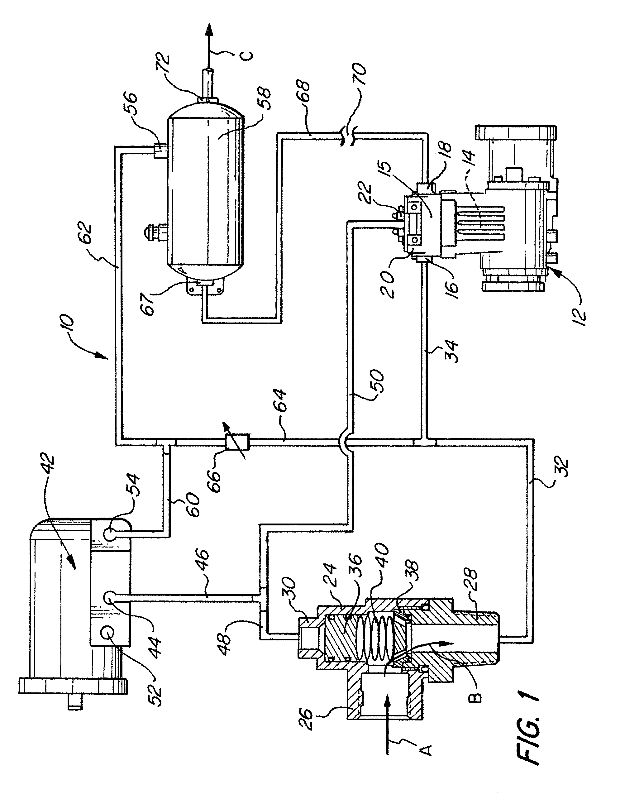
[0032]Referring first to FIG. 1, an air supply system 10 in accordance with an embodiment of the present invention is shown. Air supply system 10 includes a compressor 12 having a compression chamber 14, a compressor head 15, an inlet port 16 through which air flows into compression chamber 14 and an outlet port 18 through which air exits compression chamber 14. Compressor 12 is typically a reciprocating type compressor, and may have any of numerous known or yet to be developed configurations, the particular configuration thereof being generally unimportant to operation of the invention disclosed herein. Since numerous such compressors are extremely well-known in the art, the particular structure and operation of compressor 12 is not discussed herein in detail.

[0033]An unloader 20 causes compressor 12 to be in an unloaded state in response to a pneumatic signal being received at a signal port 22 thereof. Unloader 20 may be integrally formed as part of compressor 12 (as shown in the ...


PUM


Abstract

An air supply system includes a compressor having a compression chamber, an inlet port through which air flows into the compression chamber and an outlet port through which air exits the compression chamber, an unloader which causes the compressor to be in an unloaded state when a desired system air pressure is maintained, an isolation valve preventing inlet air from flowing into the inlet port of the compressor when the compressor is in the unloaded state, and a source of pressurized air supplying pressurized air to the inlet port of the compressor at least when the isolation valve prevents inlet air from flowing into the inlet port of the compressor.

Description

FIELD OF THE INVENTION[0001]The present invention relates generally to air supply systems using reciprocating type air compressors and, more particularly, to compressor unloading systems usable in such air supply systems, such as might be found in air supply systems for truck air brakes and the like.BACKGROUND OF THE INVENTION[0002]It is well known in the art that in air supply systems, such as might be found in air supply systems for truck air brakes and the like, the air compressor operates in its pumping mode for only a relatively short period of time, and that it is operated in what is known as an unloaded mode for as much as approximately 70-90 percent of the time. How to unload the air compressor to save horsepower when the compressor is not pumping, without having other problems occur, has been a long standing problem in the art.[0003]Air compressors used in medium and heavy duty vehicle air supply systems, such as those found in transport trucks, passenger buses, and the lik...

Claims


Application Information

Patent Timeline
IPC IPC(8): F04B49/00
CPCB60T17/04B60T17/02B60T17/00F15B11/00F15B11/06
Inventor BOCKELMAN, KATHLEEN MICHELLESCHAAKE, MARK DWANE
Owner HALDEX BRAKE
Why Eureka
Try Eureka