Folding Flue

Inactive Publication Date: 2009-08-13
OLYMPIA CHIMNEY SUPPLY
View PDF17 Cites 3 Cited by
  • Summary
  • Abstract
  • Description
  • Claims
  • Application Information

AI Technical Summary

Benefits of technology

[0018]It is an object of the present invention to produce a chimney flue which is more economical to manufacture.
[0019]It is another object of the present invention to produce a chimney flue which is more economical to ship through the postal system.
[0020]It is another object of the present inv

Problems solved by technology

Most prior art flues were at least partially assembled and therefore large and bulky to mail to chimney installers.
Since they are typically lar

Method used


Image

  • Folding Flue
  • Folding Flue
  • Folding Flue

Examples


Example

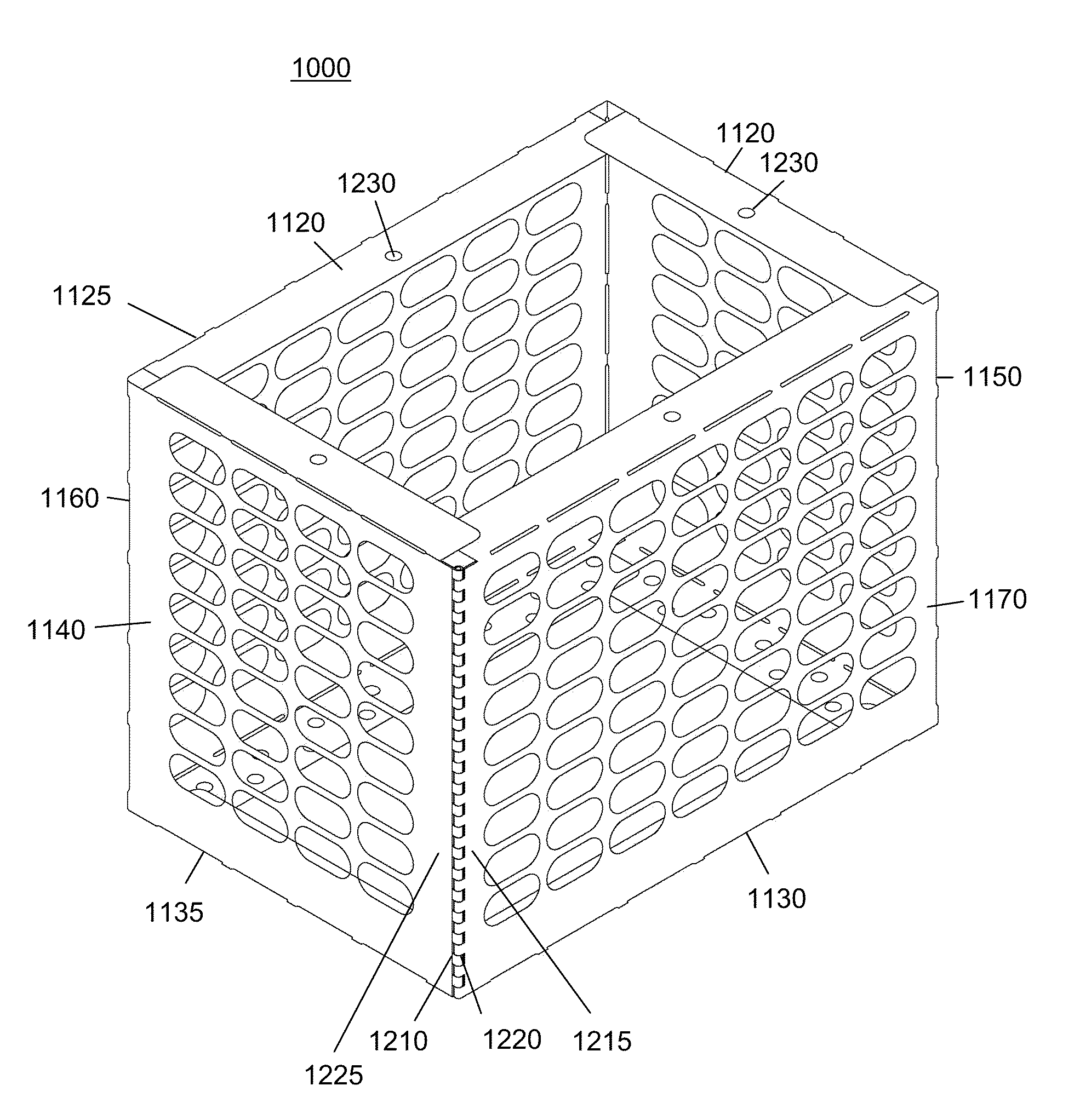
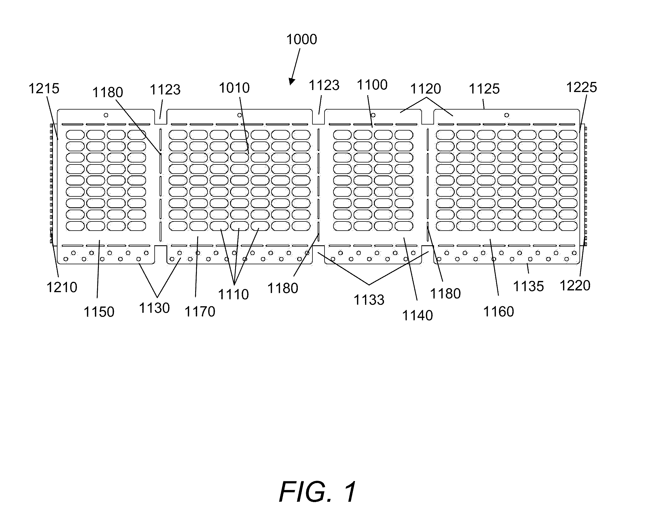
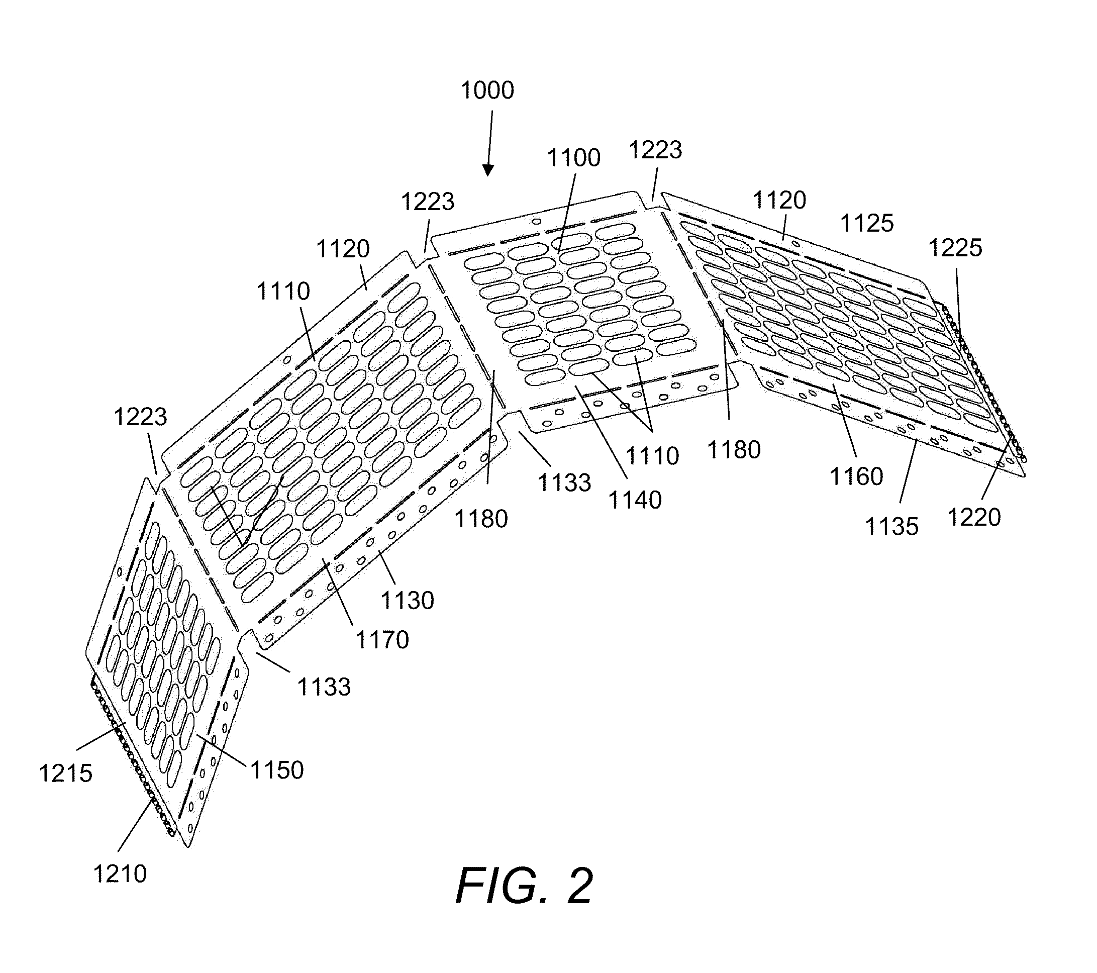
[0031]FIG. 1 is a plan view of one embodiment of a folding flue according to the present invention as it would be shipped. A body [1100] is shown in its unfolded flat view. Body [1100] has vent holes [1110] cut into it.

[0032]Body [1100] has stamped or perforated or otherwise weakened fold lines [1180]. Fold lines [1180] are a narrow area of reduced strength. These fold lines [1180] are typically constructed by running a roller blade over a metal sheet thereby producing indentations and a thinned area. Here they are created by cutting slots. When a sheet having a fold line [1180] is bent, it tends to bend at the fold line [1180] and not elsewhere on the sheet.

[0033]Body [1100] has several fold lines [1180] which separate it into end panels [1140, 1150], and side panels [1160, 1170]. Each of these panels has a top tab [1120] and a bottom tab [1130].

[0034]A first connector part [1210] is attached to one end of body [1100] and a second connector part [1220] is attached to the other end ...


PUM


Abstract

The present invention relates to a folding chimney flue cap [1000] for fitting chimneys. The folding flue cap [1000] is manufactured as a flat body [1100] having an end panel [1140], a side panel [1160], another end panel [1150], and another side panel [1170], separated by fold lines [1180] between the panels. The folding chimney flue cap [1000] also includes top tabs [1120] above each of these panels. There are also bottom tabs [1130] below each of these panels. The flat body [1100] has a first connector part [1210] at one end and a second connector part [1220] on the other end. The folding flue cap [1000] may be readily shipped in its compact form and assembled into a box shape connecting first connector part [1210] to second connector part [1220]. The top tabs [1120] and the bottom tabs [1130] may be bent either inwardly or outwardly to better match the structures to which it would connect.

Description

CROSS REFERENCE TO RELATED APPLICATIONS[0001]This application claims priority from U.S. Provisional Patent Application Ser. No. 60 / 997,276 “Folding Flue Cap” filed Oct. 2, 2007 by the same inventors as the present application, George W. Howard, Eric Depue, Ray Rerick. The present application claims priority from this application as if it were set forth in its entirety herein.FEDERAL SPONSORED RESEARCH[0002]Not ApplicableSEQUENCE LISTING OR PROGRAM[0003]Not ApplicableBACKGROUND OF THE INVENTION[0004]1. Field of the Invention[0005]The present invention relates to chimney flues and more specifically to foldable chimney flues.[0006]2. Discussion of Related Art[0007]A chimney has an opening running its length for conveying exhaust gases from a fireplace, furnace or boiler acting as a heating source. Chimneys typically have a liner which runs from a furnace up through the chimney which exits on the roof. A top plate usually secures the liner to the chimney. A top flue cap or top cap may b...

Claims


Application Information

Patent Timeline
IPC IPC(8): F23J13/06
CPCF23J13/08F23J2213/303F23L17/02F23J2900/13022F23J2900/13005
Inventor HOWARD, GEORGE W.DEPEW, ERIC C.RERICK, RAY A.
Owner OLYMPIA CHIMNEY SUPPLY
Why Eureka
Try Eureka