Micromechanical component and method for manufacturing a micromechanical component

Inactive Publication Date: 2015-02-26
ROBERT BOSCH GMBH
View PDF2 Cites 5 Cited by
  • Summary
  • Abstract
  • Description
  • Claims
  • Application Information

AI Technical Summary

Benefits of technology

[0005]An object of the present invention is therefore to furnish a micromechanical component and a method for manufacturing a micromechanical component, th

Problems solved by technology

With the known assemblages, microelectromechanical (MEMS) structures are, for example attached to the substrate of an MEMS element in such a way that, for example, encapsulating an MEMS element in a molding compound and/or soldering the MEMS element onto a circuit b

Method used


Image

  • Micromechanical component and method for manufacturing a micromechanical component
  • Micromechanical component and method for manufacturing a micromechanical component
  • Micromechanical component and method for manufacturing a micromechanical component

Examples


Example

[0035]In the various Figures, identical parts are always labeled with the same reference characters and are therefore as a rule also each recited or mentioned only once.

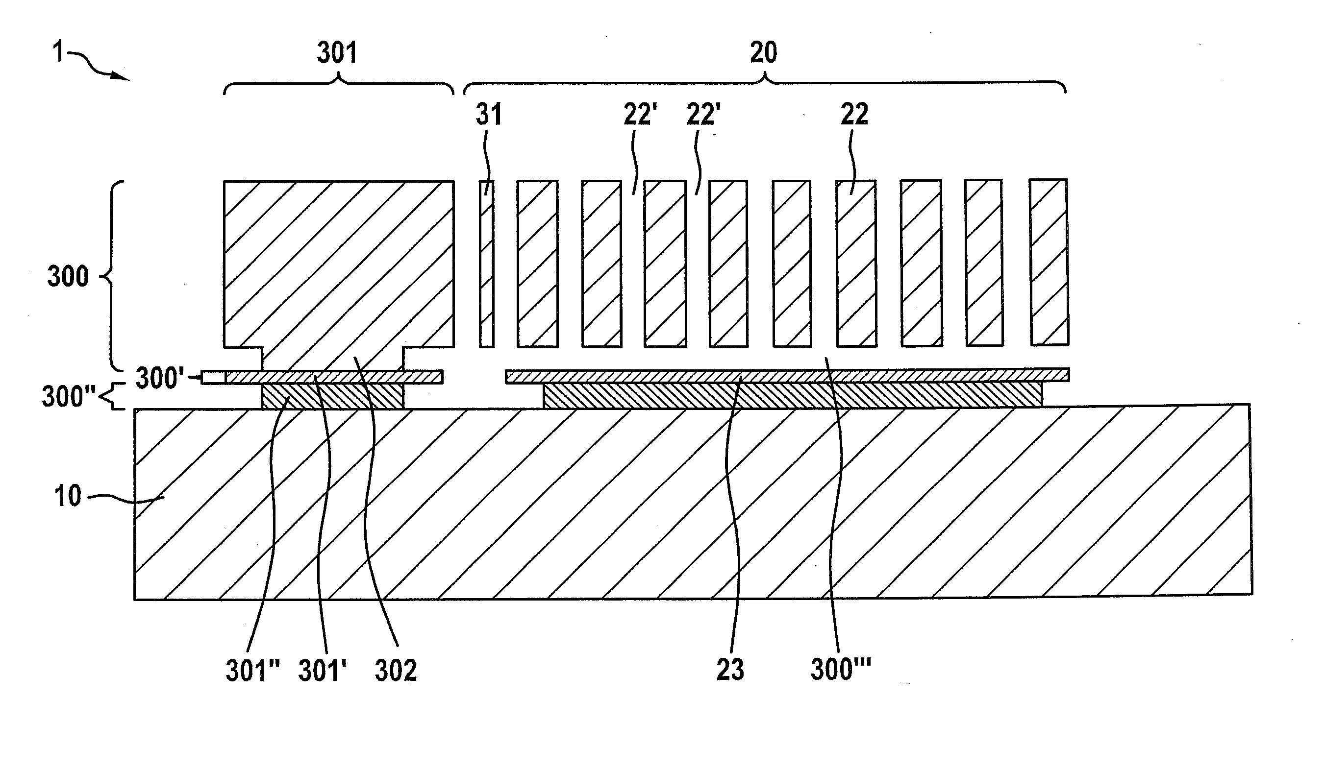
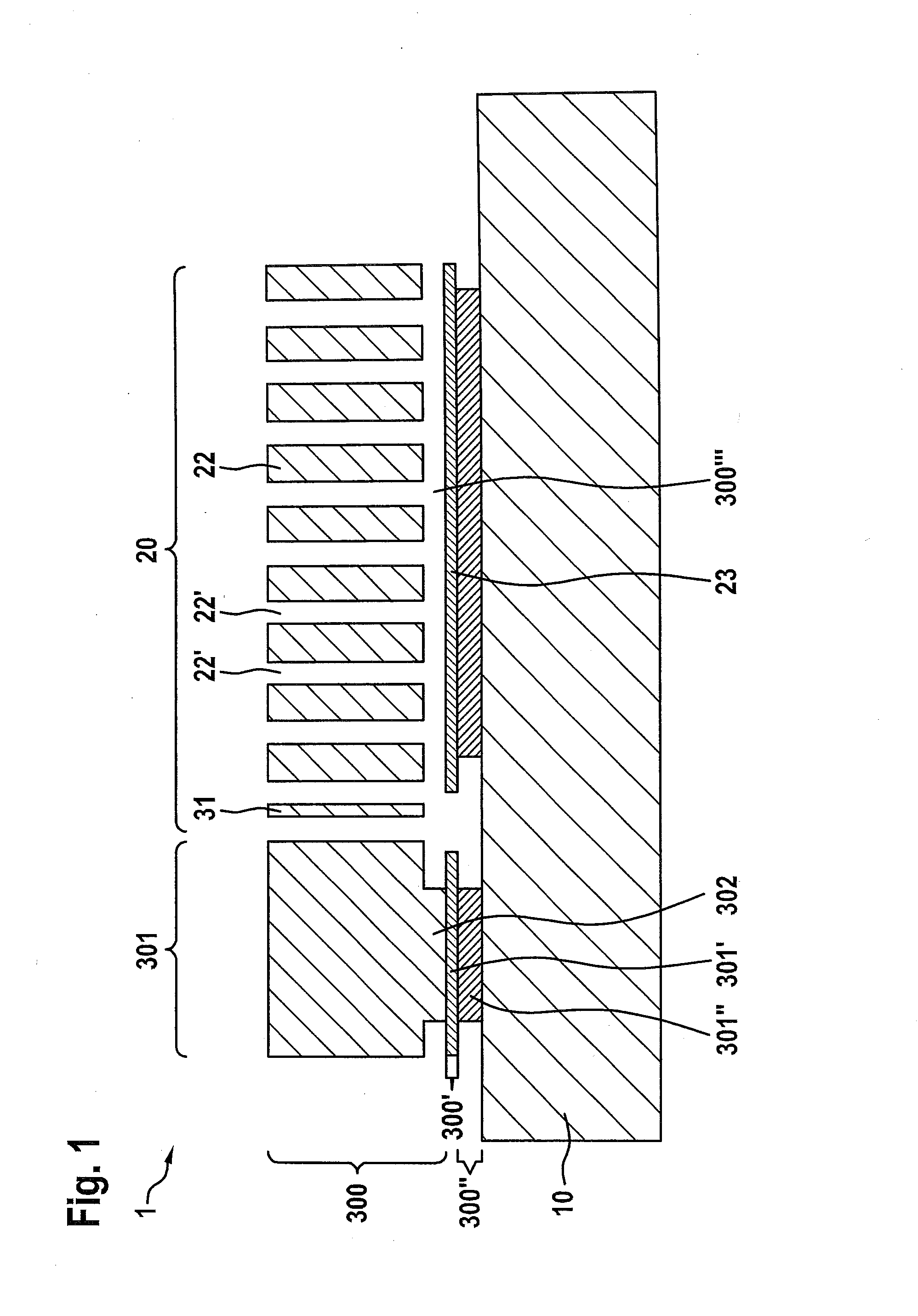
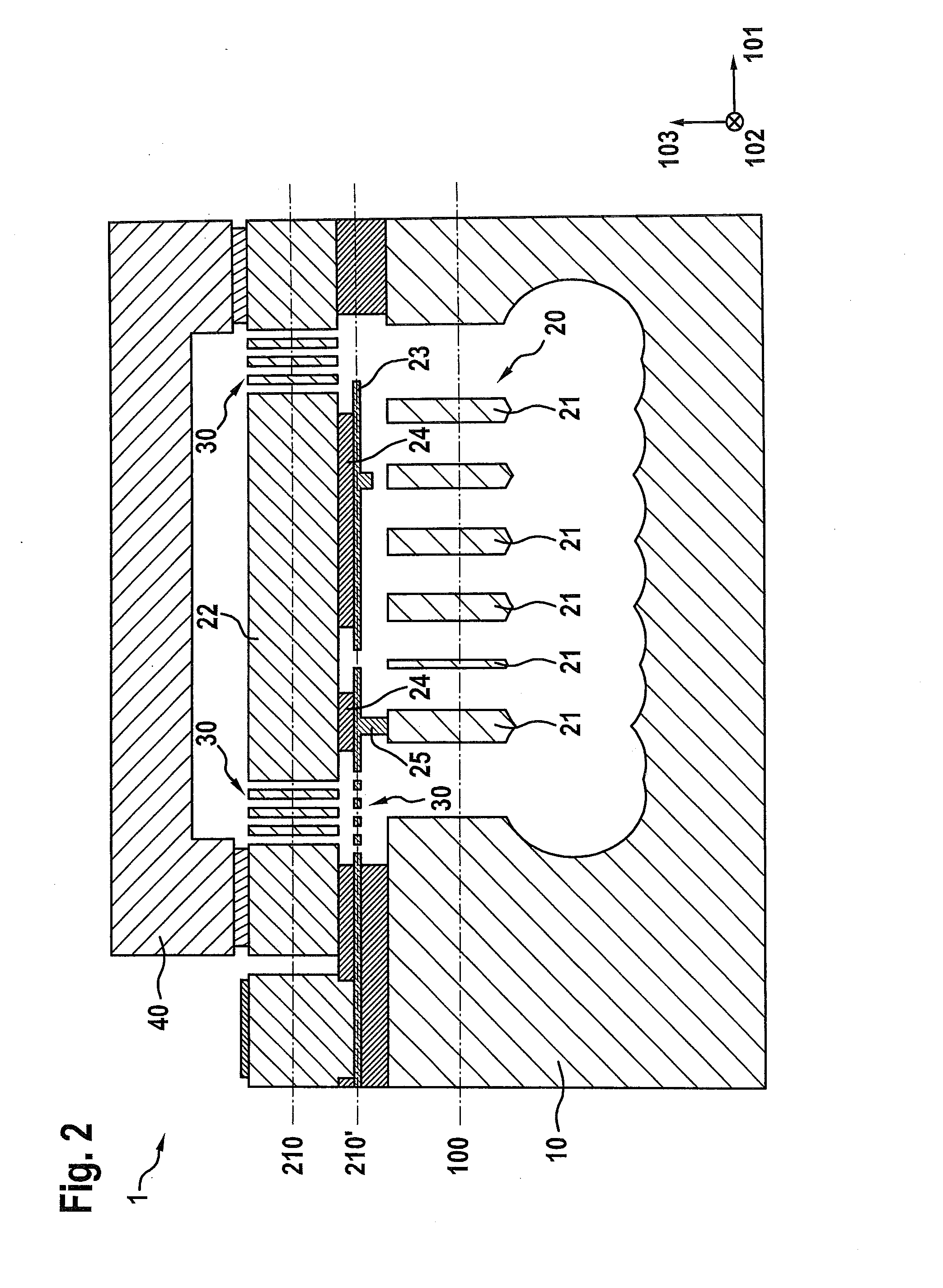
[0036]In the various Figures, a first direction 101 substantially parallel to main plane of extension 100 of the substrate is referred to as X direction 101, a second direction 102 substantially parallel to main plane of extension 100 and substantially perpendicular to X direction 101 is referred to as Y direction 102, and a third direction 103 substantially perpendicular to main plane of extension 100 is referred to as Z direction 103 or normal direction 103.

[0037]FIG. 1 depicts an embodiment of micromechanical component 1 of the present invention. A micromechanical component of this kind is, for example, an acceleration sensor and / or a rotation rate sensor. The micromechanical component has a movable element 20, movable element 20 being deflectable out of a rest position, i.e. a rest location, into a deflected posi...


PUM

PropertyMeasurementUnit
Thicknessaaaaaaaaaa

Abstract

A micromechanical component comprising a substrate having a main plane of extension, comprising a movable element, and comprising a spring arrangement assemblage is provided, the movable element being attached to the substrate by way of the spring arrangement assemblage, the movable element being deflectable out of a rest position into a deflection position, the movable element encompassing a first sub-element and a second sub-element connected to the first sub-element, the first sub-element extending mainly along the main plane of extension of the substrate, the second sub-element extending mainly along a functional plane, the functional plane being disposed substantially parallel to the main plane of extension of the substrate, the functional plane being spaced away from the main plane of extension.

Description

RELATED APPLICATION INFORMATION[0001]The present application claims priority to and the benefit of German patent application no. 10 2013 216 901.9, which was filed in Germany on Aug. 26, 2013, the disclosure of which is incorporated herein by reference.FIELD OF THE INVENTION[0002]The present invention proceeds from a micromechanical component.BACKGROUND INFORMATION[0003]Micromechanical components of this kind, and methods for manufacturing them, are commonly known. For example, methods for manufacturing micromechanical sensors, such as acceleration sensors and rotation rate sensors, are commonly known.[0004]With the known assemblages, microelectromechanical (MEMS) structures are, for example attached to the substrate of an MEMS element in such a way that, for example, encapsulating an MEMS element in a molding compound and / or soldering the MEMS element onto a circuit board can result in substrate warping, warping of individual MEMS structures, and / or undesired erroneous signals from...

Claims


Application Information

Patent Timeline
IPC IPC(8): B81B3/00B81C1/00
CPCB81C1/00825B81B3/0078B81B7/0016B81B2201/0235B81B2201/0242
Inventor REINMUTH, JOCHEN
Owner ROBERT BOSCH GMBH
Why Eureka
Try Eureka