Method for packaging a spectacle lens

a technology of spectacle lens and packaging method, which is applied in the direction of instruments, packaged goods, shock-sensitive objects, etc., can solve the problems of high risk of degrading the surface state of said convex face, and achieve the effect of low cost, no complicated manipulation requiring precision, and simple and rapid operation

Active Publication Date: 2021-05-04
ESSILOR INT CIE GEN DOPTIQUE
View PDF14 Cites 0 Cited by
  • Summary
  • Abstract
  • Description
  • Claims
  • Application Information

AI Technical Summary

Benefits of technology

[0059]In one embodiment the strip is of elastomer, for example a foam, having a folded end and able to come to adhere to a face of the lens that is opposite the convex face. In this way, the folded end can itself be glued to the lens. This folded end has a very short length and preferably extends over less than 10% of the radius of the lens if the latter were circular, or less than 5% of the greatest dimension of said lens if the latter had some other shape.
[0060]A packaging method according to the invention has the advantage of being simple and rapid to carry out in that it necessitates no specific tooling and no complicated manipulation requiring precision. It has moreover the advantage of being reversible in as simple and rapid a manner, allowing return of the lens to its original state, without causing the slightest modification to appear at the level of its structure or its surface state. It finally has the advantage of being of relatively low cost because it requires the use of an adhesive strip necessitating no complicated dimensions.

Problems solved by technology

Actually, in the absence of this protective strip there is nothing to prevent the wall of the envelope from coming into contact with the convex face of the lens, with a high risk of degrading the surface state of said convex face.

Method used


Image

  • Method for packaging a spectacle lens
  • Method for packaging a spectacle lens
  • Method for packaging a spectacle lens

Examples


Embodiment Construction

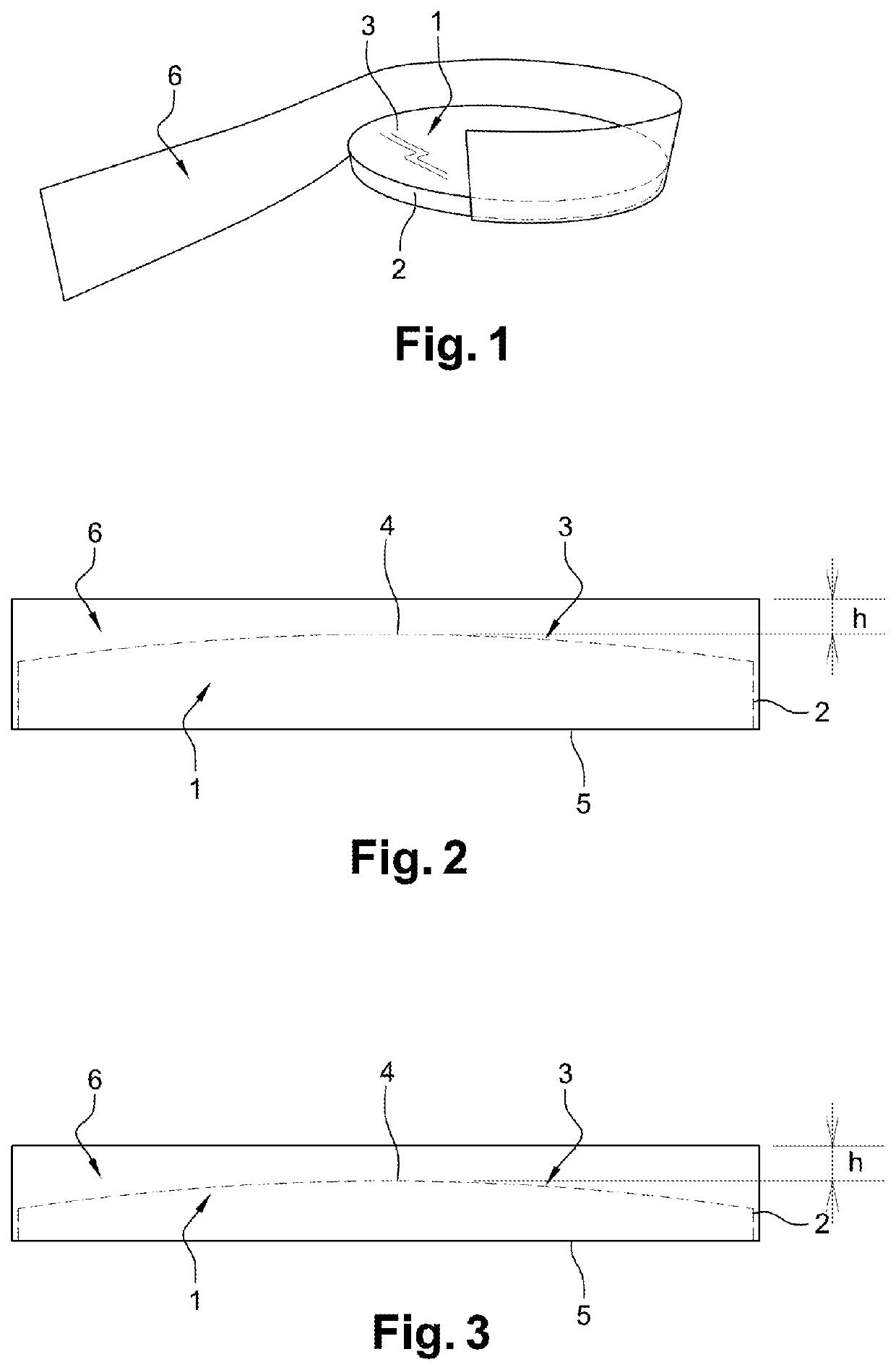
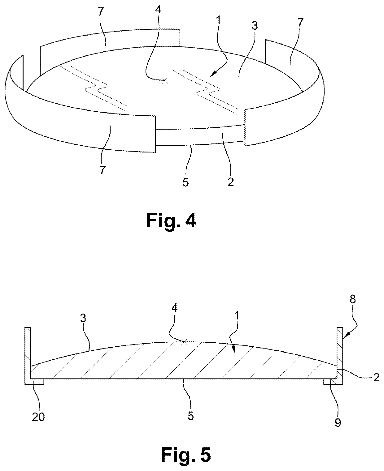
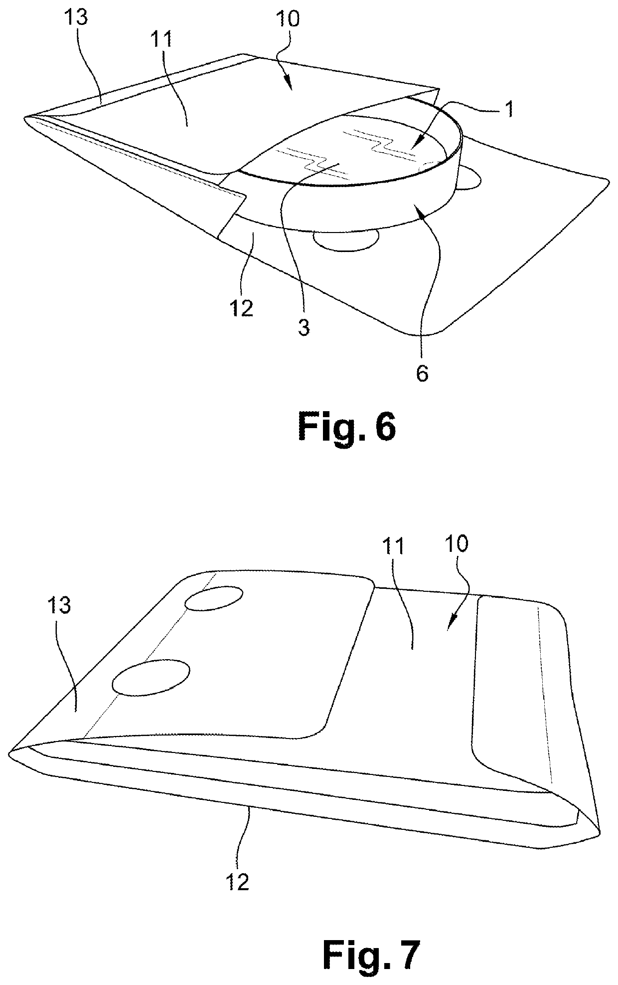
[0069]In the following detailed description, it is assumed that a protective strip is fixed to an optical lens by gluing it on. Actually, a fixing technique of this kind is particularly suited to a packaging method according to the invention.

[0070]It is moreover understood that the term “lens” employed in the present description must be understood according to the following definition: the lens referred to here corresponds to an optical article of the ophthalmic lens type, an ocular visor, and optical viewing systems. In particular an ophthalmic lens is a lens that is designed to fit a spectacle frame in order to protect the eye and / or to correct the vision and may be a non-correcting ophthalmic lens (also termed a plano or an afocal lens) or corrective. A corrective lens may be a unifocal, bifocal, trifocal or progressive lens. The ophthalmic lens may be a finished lens or a semi-finished lens, intended to be reworked by machining one of its principal faces in order to impart a pre...


PUM

PropertyMeasurementUnit
tensionaaaaaaaaaa
widthaaaaaaaaaa
widthaaaaaaaaaa

Abstract

Disclosed is a method for packaging an optical lens including two faces and a peripheral edge, at least one of the faces having a convexity marked by a peak point, the method including the following steps: a step of depositing a protective strip made from a rigid material at least partially along the edge, the width of the strip extending beyond the peak point of the convex face of the lens; a step of inserting the lens into an envelope delimited by a wall; a step of positioning the lens in the envelope, such that the protective strip acts as a spacer in order to maintain a distance between the wall of the envelope and the convex face of the lens and thus preventing any contact between the wall and the face.

Description

BACKGROUND OF THE INVENTIONField of the Invention[0001]The invention relates to a method of packaging a spectacle lens. To be more specific, packaging of this kind is designed to facilitate the transportation and the manipulation of the lens.Description of the Related Art[0002]As a general rule, a lens intended to be mounted in a spectacle frame will inevitably undergo a transportation phase, either to be sent to a workshop where it will be machined in a more refined manner in order to be directly ready to be fixed to the appropriate frame, or if it has already been machined to be sent for example to an optician, who will then proceed to fix it to said frame.[0003]This transportation phase is made delicate because these lenses have often undergone a surface treatment, for example to prevent reflections and / or to favor a flow of water, said treatment being sensitive to any type of exterior contact. Accordingly, contact with the fingers of a hand or with the wall of transportation pac...

Claims


Application Information

Patent Timeline
Patent Type & Authority Patents(United States)
IPC IPC(8): B65B61/22B65D85/38B65D81/05B65B25/00B29D11/00G02B1/10G02C7/02A45C11/00
CPCB65B61/22B65B25/00B65D81/05B65D85/38A45C11/005B29D11/00567B29D11/00865B65B25/008B65D2585/545G02B1/10G02C7/02B65B61/20B65B23/20B65D77/24B65B5/045
Inventor HENRY, PATRICK
Owner ESSILOR INT CIE GEN DOPTIQUE
Why Eureka
Try Eureka