Method and apparatus for a shape memory implant

a shape memory and implant technology, applied in the field of surgical implants, can solve the problems of poor bone quality, lack of structural integrity, inability to impart a force adequate to properly fuse or distract the bone, bones, or bone pieces in patients exhibiting poor bone quality, etc., and achieve the effect of advancing bone quality

Active Publication Date: 2021-05-18
DEPUY SYNTHES PROD INC
View PDF17 Cites 6 Cited by
  • Summary
  • Abstract
  • Description
  • Claims
  • Application Information

AI Technical Summary

Benefits of technology

[0018]Still other objects, features, and advantages of the present invention will become evident to those of ordinary skill in the art in light of the following. Also, it should be understood that the scope of this invention is intended to be broad, and any combination of any subset of the features, elements, or steps described herein is part of the intended scope of the invention.

Problems solved by technology

Conversely, bone, bones, or bone pieces in patients exhibiting a poorer bone quality, due to osteoporosis, trauma, or the like, lack structural integrity sufficient to arrest movement of the legs for a surgical staple during its attempted transition from its insertion shape to its natural shape such that the surgical staple over-transitions to a leg position incapable of imparting a force adequate to properly fuse or distract the bone, bones, or bone pieces.
As a consequence, the bone, bones, or bone pieces experience a loss of fixation that may result in an improper fusion or distraction of the bone, bones, or bone pieces.

Method used


Image

  • Method and apparatus for a shape memory implant
  • Method and apparatus for a shape memory implant
  • Method and apparatus for a shape memory implant

Examples


first embodiment

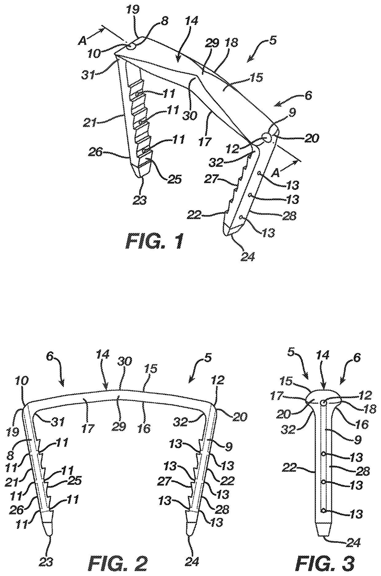
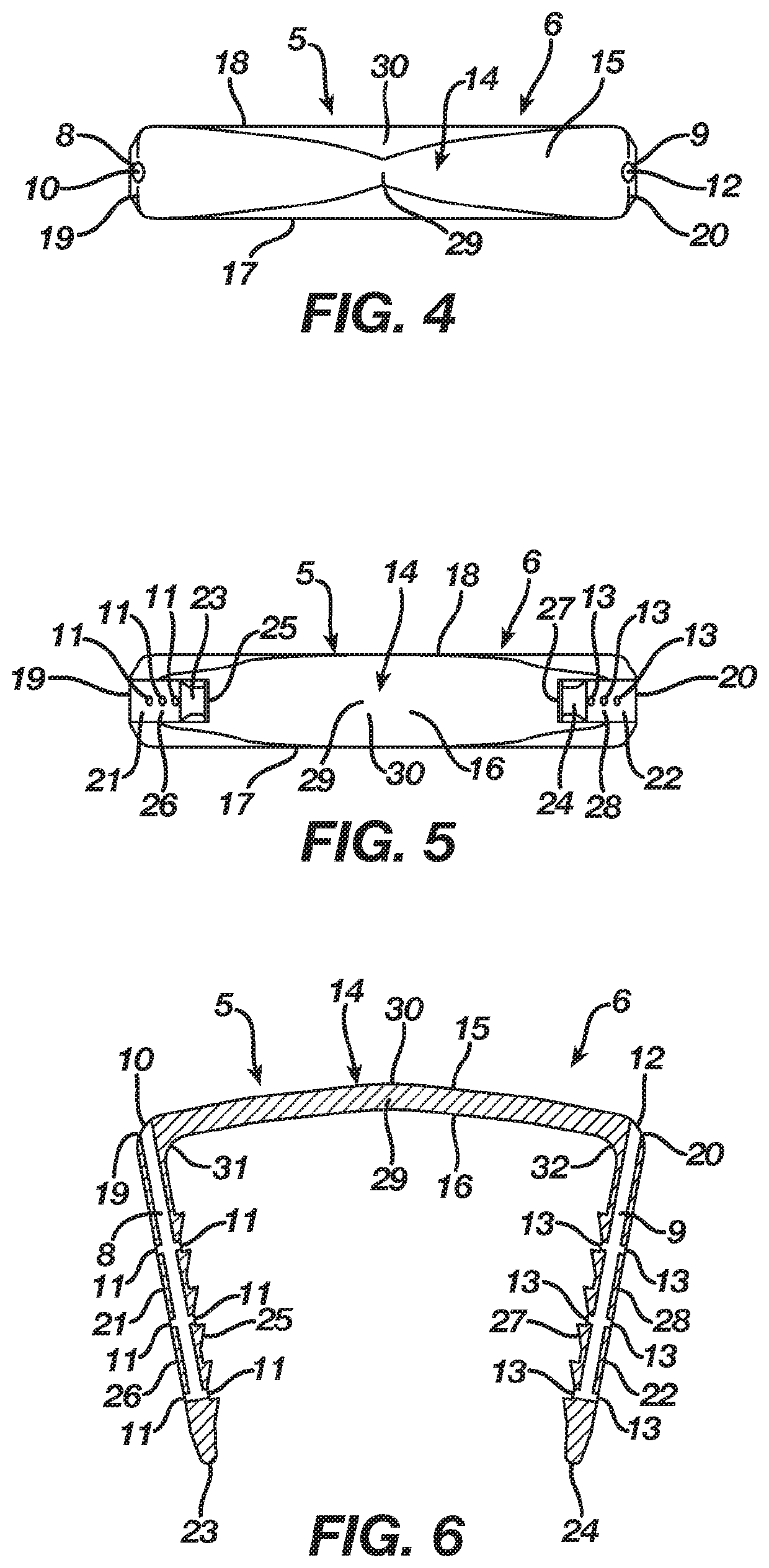
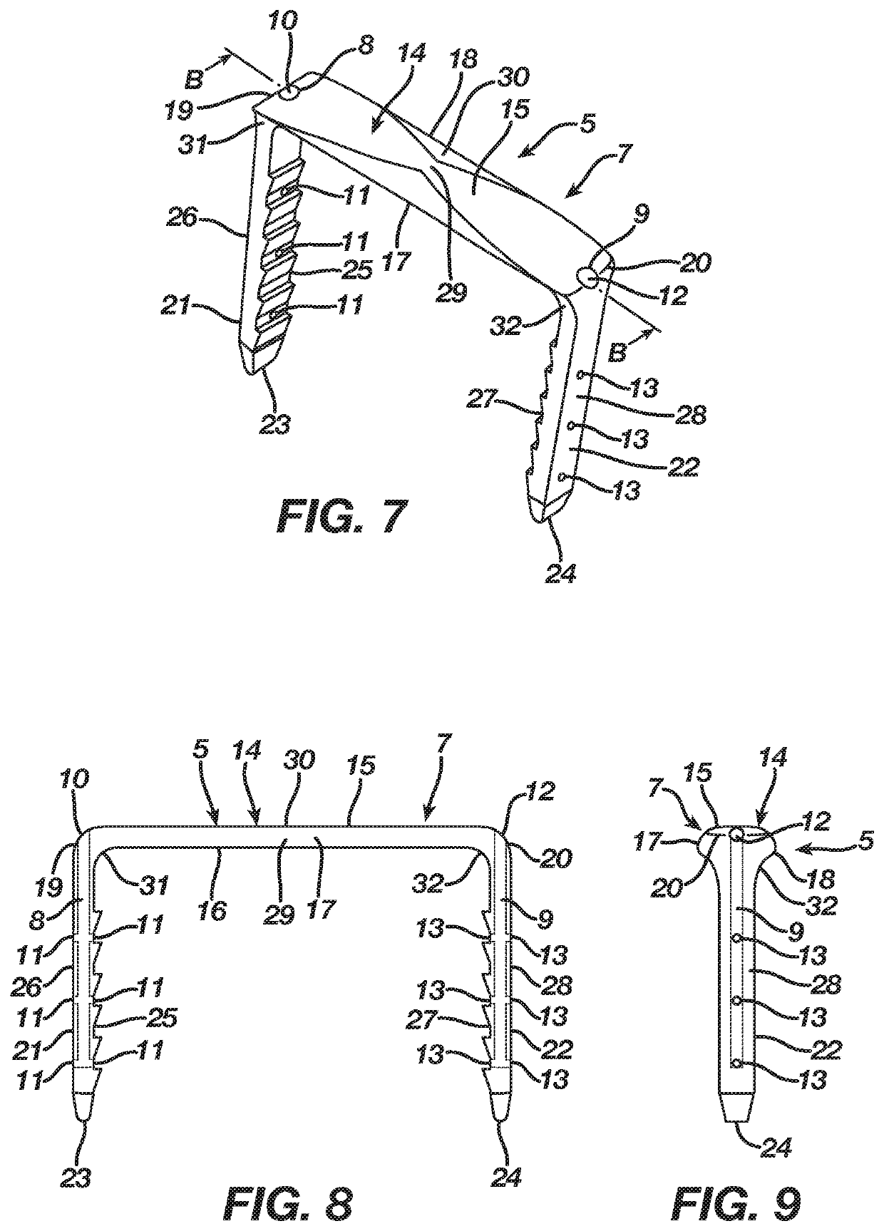
[0082]Alternatively, the bridge 14 in the first embodiment may include transition sections 31 and 32 located respectively where the legs 21 and 22 extend from the bridge 14. The regular inherent shape of the implant 5, as illustrated in FIGS. 1-6, is its natural shape 6 where the transition sections 31 and 32 locate the bridge 14 in a natural form that places the legs 21 and 22 in a natural position whereby the legs 21 and 22 are convergent and spaced apart at a first distance. Nevertheless, as illustrated in FIG. 13, the implant 5 is deformable under the action of superelasticity or temperature dependent shape memory to an insertion shape 7 where the transition sections 31 and 32 deform to store energy while also moving the bridge 14 from its natural form to an insertion form that places the legs 21 and 22 in an insertion position whereby the legs 21 and 22 are substantially parallel and spaced apart at a second distance that is greater than the first distance. Since the insertion ...

second embodiment

[0097]Alternatively, the bridge 65 in the second embodiment may include transition sections 82 and 83 located respectively where the legs 75 and 76 extend from the bridge 65, and, in addition thereto when supplementary transition is desired, the bridge 65 may include transition sections 84 and 85 located respectively where the legs 73 and 74 extend from the bridge 65. The regular inherent shape of the implant 50, as illustrated in FIGS. 16-21, is its natural shape 51 where the transition sections 82 and 83 and if included the transition sections 84 and 85 locate the bridge 65 in a natural form that places the legs 73-76 in a natural position whereby the legs 73 and 75 are convergent with and spaced apart at a first distance from the legs 74 and 76. Nevertheless, as illustrated in FIG. 28, the implant 50 is deformable under the action of superelasticity or temperature dependent shape memory to an insertion shape 52 where the transition sections 82 and 83 and if included the transitio...

third embodiment

[0111]Alternatively, the bridge 114 in the third embodiment may include transition sections 131 and 132 located respectively where the legs 121 and 122 extend from the bridge 114. The regular inherent shape of the implant 105, as illustrated in FIGS. 31-36, is its natural shape 106 where the transition sections 131 and 132 locate the bridge 114 in a natural form that places the legs 121 and 122 in a natural position whereby the legs 121 and 122 are convergent and spaced apart at a first distance. Nevertheless, as illustrated in FIG. 43, the implant 105 is deformable under the action of superelasticity or temperature dependent shape memory to an insertion shape 107 where the transition sections 131 and 132 deform to store energy while also moving the bridge 114 from its natural form to an insertion form that places the legs 121 and 122 in an insertion position whereby the legs 121 and 122 are substantially parallel and spaced apart at a second distance that is greater than the first ...


PUM


Abstract

An apparatus for fixating bone includes an orthopedic implant. The orthopedic implant may be manufactured from a shape memory material such that the orthopedic implant is moveable between a natural shape and an insertion shape. The orthopedic implant defines at least a first cannulation therethrough adapted to deliver a bone augmentation material to the bone. The orthopedic implant implants into the bone in its insertion shape. After implantation of the orthopedic implant, the first cannulation facilitates delivery into the bone of a bone augmentation material that augments the bone. The orthopedic implant once implanted attempts to transition from its insertion shape to its natural shape such that the orthopedic implant fixates the bone.

Description

BACKGROUND OF THE INVENTION1. Field of the Invention[0001]The present invention relates to surgical implants suitable for use in affixing bone, bones, or bone pieces and, more particularly, but not by way of limitation, to a method and apparatus for a shape memory implant that affixes bone, bones, or bone pieces in order to fuse or distract the bone, bones, or bone pieces and promote a healing thereof.2. Description of the Related Art[0002]Shape memory materials such as nitinol (nickel-titanium) due to their superelastic or temperature dependent properties currently are employed in the manufacture of surgical implants designed to affix bone, bones, or bone pieces. A surgical implant manufactured from a shape memory material with superelastic or temperature dependent properties typically includes a natural shape. Nevertheless, the surgical implant may be deformed from its natural shape to an insertion shape whereby the surgical implant stores energy deliverable to a bone, bones, or b...

Claims


Application Information

Patent Timeline
Patent Type & Authority Patents(United States)
IPC IPC(8): A61B17/06A61B17/064A61B17/068A61B17/88A61B17/10A61B17/00
CPCA61B17/0642A61B17/068A61B17/8872A61B17/10A61B2017/00526A61B2017/00867A61B2017/0645A61B17/84A61B17/844A61B17/885A61B17/0682A61B17/8811A61B2017/0641A61B2017/561A61L31/022A61L31/14A61L31/16A61L2400/16A61L2430/02
Inventor DANIEL, STEFFAN
Owner DEPUY SYNTHES PROD INC
Why Eureka
Try Eureka