
Partial dismantling device of photovoltaic module

a technology of photovoltaic modules and dismantling devices, which is applied in the direction of reversed direction vortex, grain treatment, vortex flow apparatus, etc., can solve the problems of photovoltaic module front glass substrate damage, photovoltaic module needs to be discarded, and can be easily damaged, so as to improve efficiency, prevent the bouncing of damaged glass pieces, and classify copper ribbons. easy

Active Publication Date: 2018-05-17
KOREA INST OF ENERGY RES
View PDF7 Cites 13 Cited by
  • Summary
  • Abstract
  • Description
  • Claims
  • Application Information

AI Technical Summary

Benefits of technology

The present invention provides a partial dismantling device for photovoltaic modules that can recycle damaged glass substrate. The device can accurately define a grinding region and separate waste and recovered material using multiple level grinders. Additionally, the device can perform detailed classification by a classifying process using a plurality of cyclones, improving the efficiency of the subsequent classifying process. The grinding unit is driven at a height higher than the glass substrate to prevent bouncing of damaged glass pieces. The device can be applied to a broader scope for recycling targets.

Problems solved by technology

A photovoltaic cell as a basic unit for a crystalline photovoltaic module is an element which can be easily damaged.
Such photovoltaic module needs to be discarded as time elapse due to reduced efficiency or the like.
Furthermore, the front glass substrate of the photovoltaic module may be damaged depending on the conditions of using or removing the photovoltaic module.
However, when the photovoltaic module is separated using a rotary brush irrespective of the element layer types, the film of the photovoltaic cell will be removed without maintaining the shape of the photovoltaic module, causing failure in partially dismantling the photovoltaic module, and causing damages on a dismantling device as glass pieces are introduced to the dismantling device.

Method used


Image

  • Partial dismantling device of photovoltaic module
  • Partial dismantling device of photovoltaic module
  • Partial dismantling device of photovoltaic module

Examples


Embodiment Construction

[0034]Hereinafter, the present invention will be described in detail with reference to the accompanying drawings. However, the present invention is not limited or restricted by exemplary embodiments. The same reference numerals represented in each of the drawings indicate the elements or the components that perform substantially the same functions.

[0035]The object and effect of the present invention will be understood naturally or be apparent by the following description, but is not limited only to the following description. In addition, a detailed description about the well known technology which may obscure the gist of the present invention unnecessarily may be omitted.

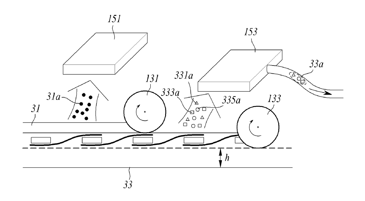
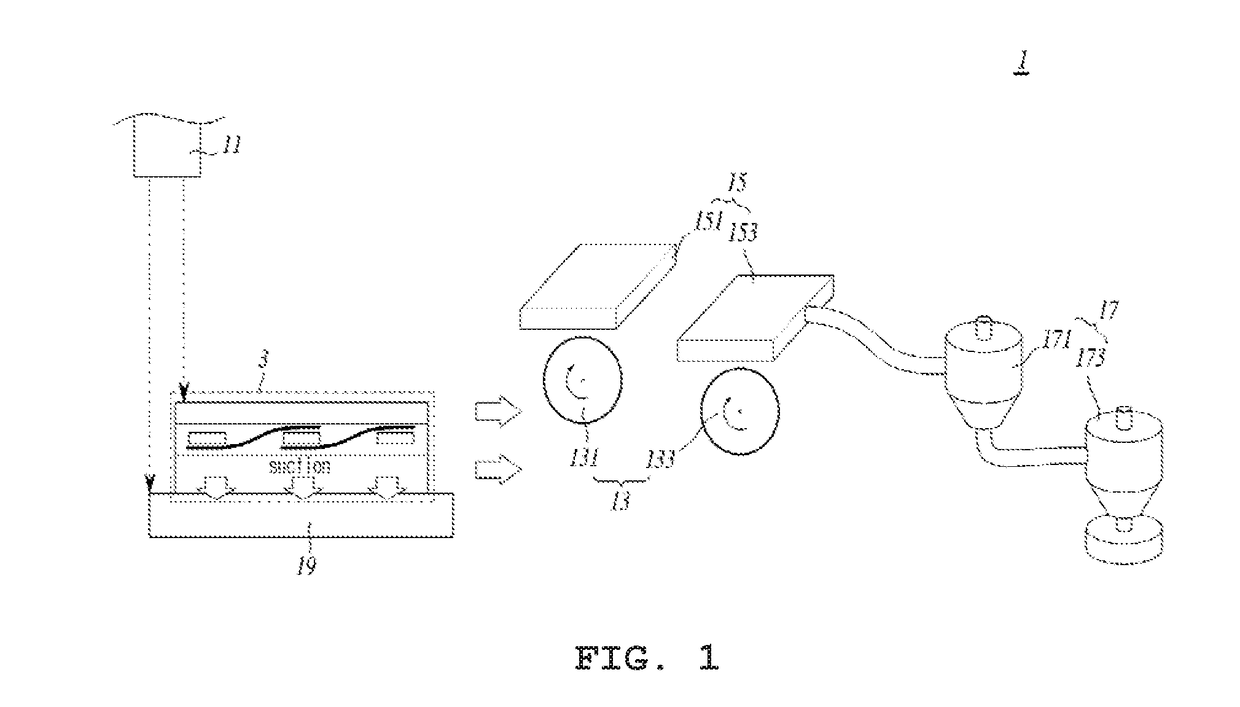
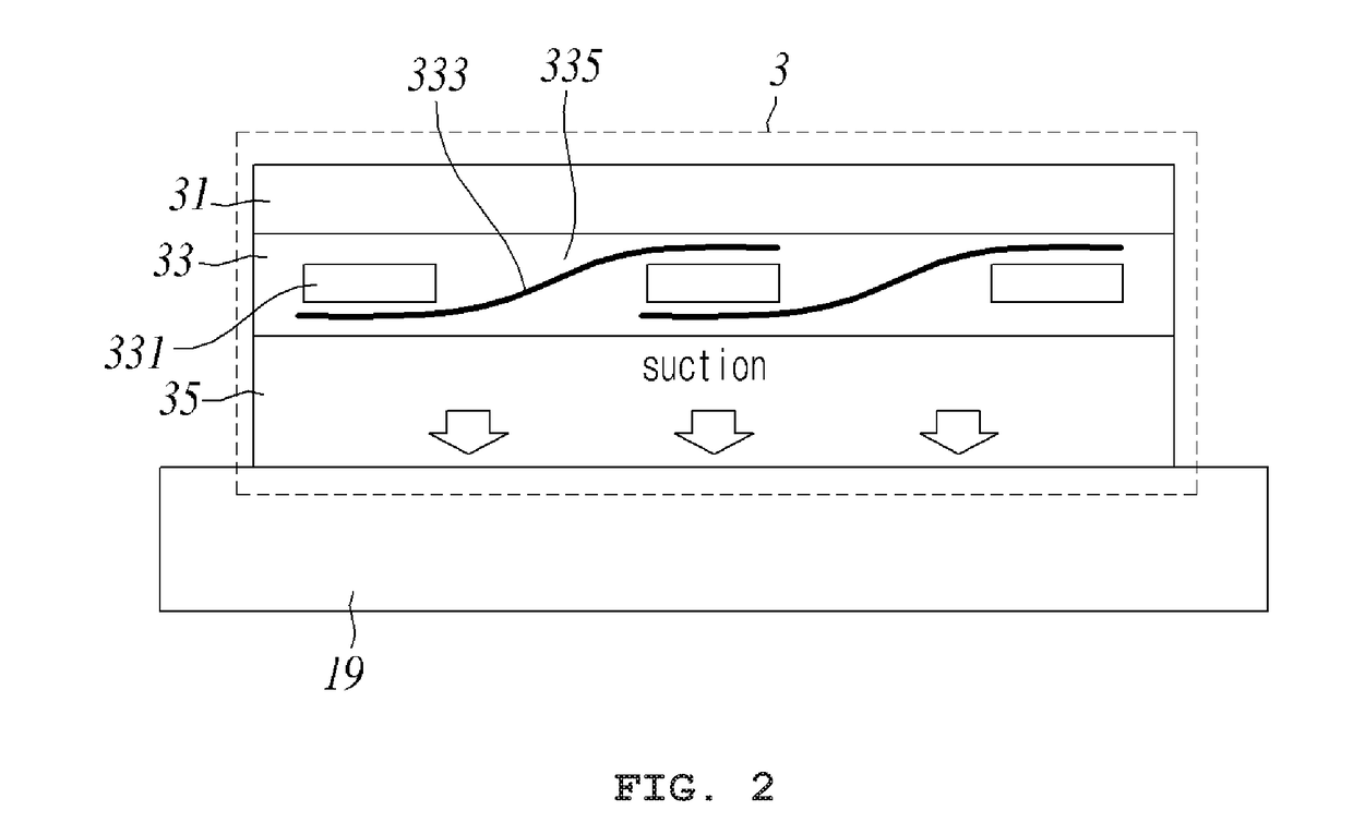
[0036]FIG. 1 shows a partial dismantling device of a photovoltaic module 1 according to an embodiment of the present invention. The partial dismantling device 1 of the photovoltaic module is provided to classify element layers of a photovoltaic module 3 and collect the same for recycling.

[0037]The partial dismantlin...


PUM


Abstract

Disclosed is a partial dismantling device of a photovoltaic module capable of classifying and collecting the photovoltaic module for recycling the photovoltaic module which includes: a transfer unit for transferring a photovoltaic module; a sensor unit for distinguishing grinding heights of the photovoltaic module arranged on the transfer unit; a grind unit provided with a plurality of grinders in multiple levels, to grind the element layers of a grinding region into particles of collectible forms; and a suction unit provided with a plurality of inhalers respectively corresponding to the plurality of grinders, to classify the particles pulverized by the grind unit and to inhale the same. Thereby, the present invention may improve the efficiency in the subsequent classifying process of the photovoltaic module particles in a classifying unit, with an advantage of applying the partial dismantling device of the photovoltaic module irrespective of damages on a glass substrate.

Description

FIELD OF THE INVENTION[0001]The present invention relates to a partial dismantling device of a photovoltaic module for recycling the photovoltaic module.BACKGROUND OF THE INVENTION[0002]A photovoltaic cell as a basic unit for a crystalline photovoltaic module is an element which can be easily damaged. Therefore, the photovoltaic cell is generally modularized within a rigid aluminum frame to be protected against external forces or bad weather conditions. The photovoltaic module is a product prepared in a single photovoltaic panel form, by laminating element layers such as a tempered glass, a filler, a photovoltaic cell, a back sheet and the like, followed by connecting cables and a switch board.[0003]The photovoltaic module includes a plurality of photovoltaic cells which are connected in series or in parallel so as to be used as a basic unit for the solar power generation. The photovoltaic module may be categorized into a crystalline photovoltaic module (the first generation), a thi...

Claims


Application Information

Patent Timeline
Patent Type & Authority Applications(United States)
IPC IPC(8): B02C23/30H01L31/18B02C4/02B02C23/38B02C25/00B02C23/10
CPCB02C23/30H01L31/18B02C4/02B02C23/38B02C25/00B02C23/10B02C23/14B09B3/00B09B5/00H01L31/042B04C5/26H01L31/048Y02E10/50B02C7/02B02C7/17H01L31/1892Y02W30/82Y02W30/20Y02W30/52
Inventor LEE, JIN-SEOKAHN, YOUNG-SOOKANG, GI-HWAN
Owner KOREA INST OF ENERGY RES
Learn More