
System and method for optimizing signal path calibration

a signal path and optimization method technology, applied in the direction of transmission, electrical equipment, transmission monitoring, etc., can solve the problems of high measurement uncertainty, significant complications imposed by thermal power meters on path calibration, and require extremely high calibration time, so as to facilitate automatic calibration

Active Publication Date: 2021-06-08
ROHDE & SCHWARZ GMBH & CO KG
View PDF13 Cites 0 Cited by
  • Summary
  • Abstract
  • Description
  • Claims
  • Application Information

AI Technical Summary

Benefits of technology

Significantly reduces measurement uncertainty and calibration time, achieving optimized signal path calibration while ensuring compliance with 5G standards by specifying calibration accuracy and time, and improving measurement reliability.

Problems solved by technology

The use of thermal power meters imposes significant complications on path calibration since they are extremely slow and insensitive.
A non-optimized path calibration disadvantageously leads to high measurement uncertainty as well as requires extremely high calibration time.
Although the specification of BER may improve the measurement accuracy, it does not however compensate the high calibration time required to calibrate a signal path, especially for a standard with high frequency range.

Method used


Image

  • System and method for optimizing signal path calibration
  • System and method for optimizing signal path calibration
  • System and method for optimizing signal path calibration

Examples


Embodiment Construction

[0030]Reference will now be made in detail to the embodiments of the present invention, examples of which are illustrated in the accompanying drawings. Similar entities and reference numbers in different figures have been partially omitted. However, the following embodiments of the present invention may be variously modified and the range of the present invention is not limited by the following embodiments.

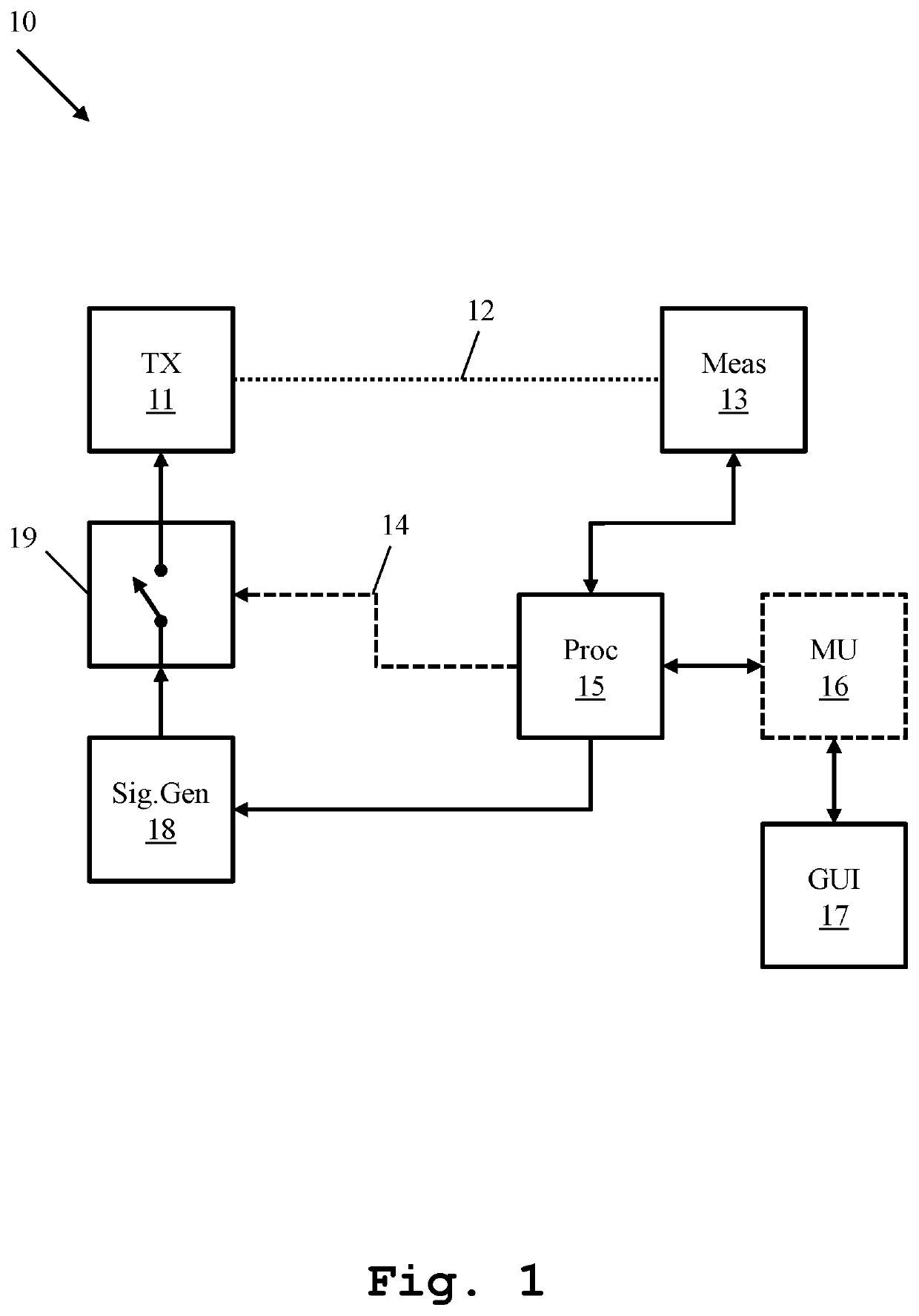
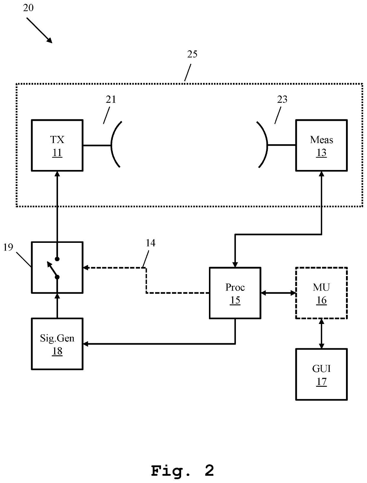
[0031]In FIG. 1, a first exemplary embodiment of the system 10 according to the first aspect of the invention is illustrated in a block diagram. The system 10 comprises a transmitting module 11 and a measuring unit 13, where a signal path 12 is formed in-between the transmitting module 11 and the measuring unit 13. The signal path 12 can be formed conductively via RF waveguides, for instance RF cables as well as in non-conductive manner. The measuring unit 13 comprises power meters, preferably thermal power meters that are typically rated above 90 GHz and perform power measurement...


PUM


Abstract

A system for optimizing signal path calibration is provided. The system comprises at least one transmitting module, at least one measuring unit, connected to the transmitting module via a signal path and a processing unit. In this context, the measuring unit is adapted to perform power measurement on the signal path. In addition, the processing unit is adapted to configure the measuring unit with respect to a predefined measurement accuracy and a predefined test time duration.

Description

TECHNICAL FIELD[0001]The invention relates to a system and a corresponding method for optimizing signal path calibration, especially for optimizing signal path calibration in Radiated Spurious Emission (RSE) measurements for fifth generation (5G) communication standards.BACKGROUND ART[0002]Spurious emissions are commonly referred to unwanted radio frequency (RF) emissions that wireless devices or systems may transmit out besides carrier frequencies. Measuring spurious emissions is very important with nearly all devices under test (DUTs) that transmit RF power since the DUTs must comply with frequency-dependent limits so that they do not interfere with other radio services or transmit unwanted signals in the case of security-relevant applications. Typical DUTs of such a system are mobile phones, base stations, radio set and short-range devices. Furthermore, the frequency spectrum is a valuable resource for service providers. It is therefore crucial that network capacity should not be...

Claims


Application Information

Patent Timeline
Patent Type & Authority Patents(United States)
IPC IPC(8): H04W24/02H04W24/08
CPCH04W24/02H04W24/08H04B17/102
Inventor BARTKO, HENDRIK
Owner ROHDE & SCHWARZ GMBH & CO KG
Learn More