Clamp of bicycle workstand

a workstand and bicycle technology, applied in the field of bicycle support frames, can solve the problems of difficult swinging up and the operation arm, and achieve the effects of stable clamping, convenient operation, and equal for

Active Publication Date: 2021-06-15
JYIN SHENG CO LTD HUATAN TOWNSHIP
View PDF3 Cites 0 Cited by
  • Summary
  • Abstract
  • Description
  • Claims
  • Application Information

AI Technical Summary

Benefits of technology

[0005]It is another objective of the present invention to provide a clamp of a bicycle workstand, which enables the angle of the bicycle clamped on the bicycle workstand to be adjusted differently from the prior art, providing the user convenience in maintaining each portion and component of the bicycle.
[0007]As a result, applying a force to the operating arm of the present invention can drive the movable clamp body to open or close relative to the fixed clamp body. When the movable clamp body and the fixed clamp body are coupled with each other to clamp the tube of the bicycle frame, the operating arm is limited by the link unit and the elastic unit and thereby difficult to swing up. For clamping bicycle frame tubes with different radius, the effects of stable clamping by equal force and convenient operation are further provided.

Problems solved by technology

When the movable clamp body and the fixed clamp body are coupled with each other to clamp the tube of the bicycle frame, the operating arm is limited by the link unit and the elastic unit and thereby difficult to swing up.

Method used


Image

  • Clamp of bicycle workstand
  • Clamp of bicycle workstand
  • Clamp of bicycle workstand

Examples


Embodiment Construction

[0016]For the detailed description of the technical features of the present invention, a preferred embodiment is given herein below and illustrated by the accompanying drawings.

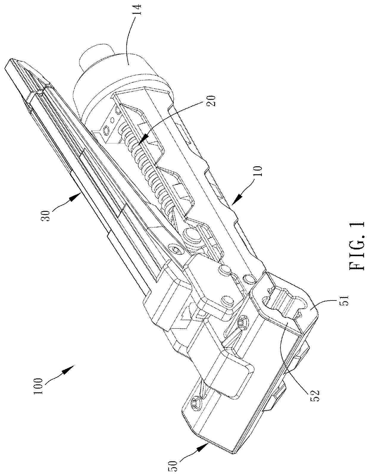
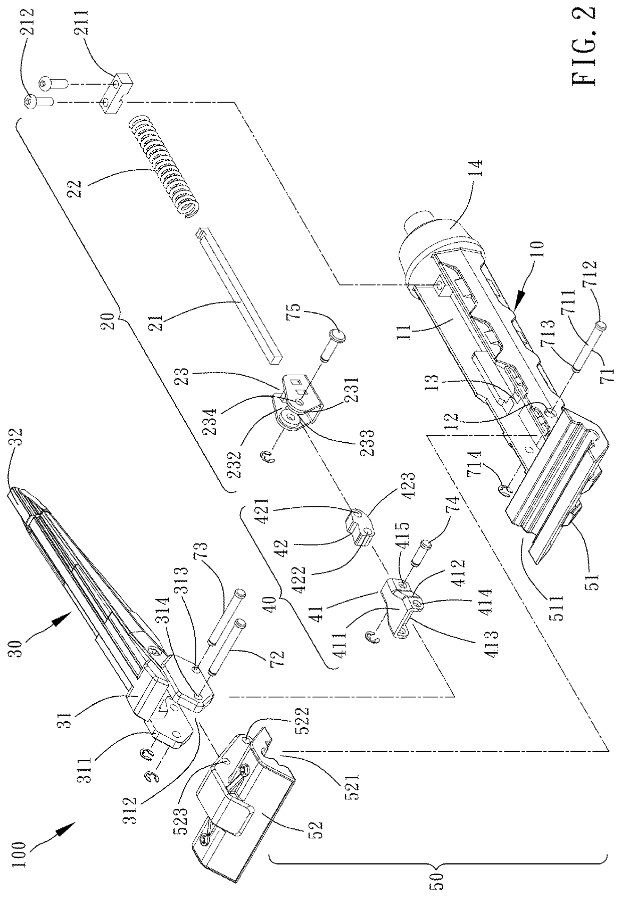
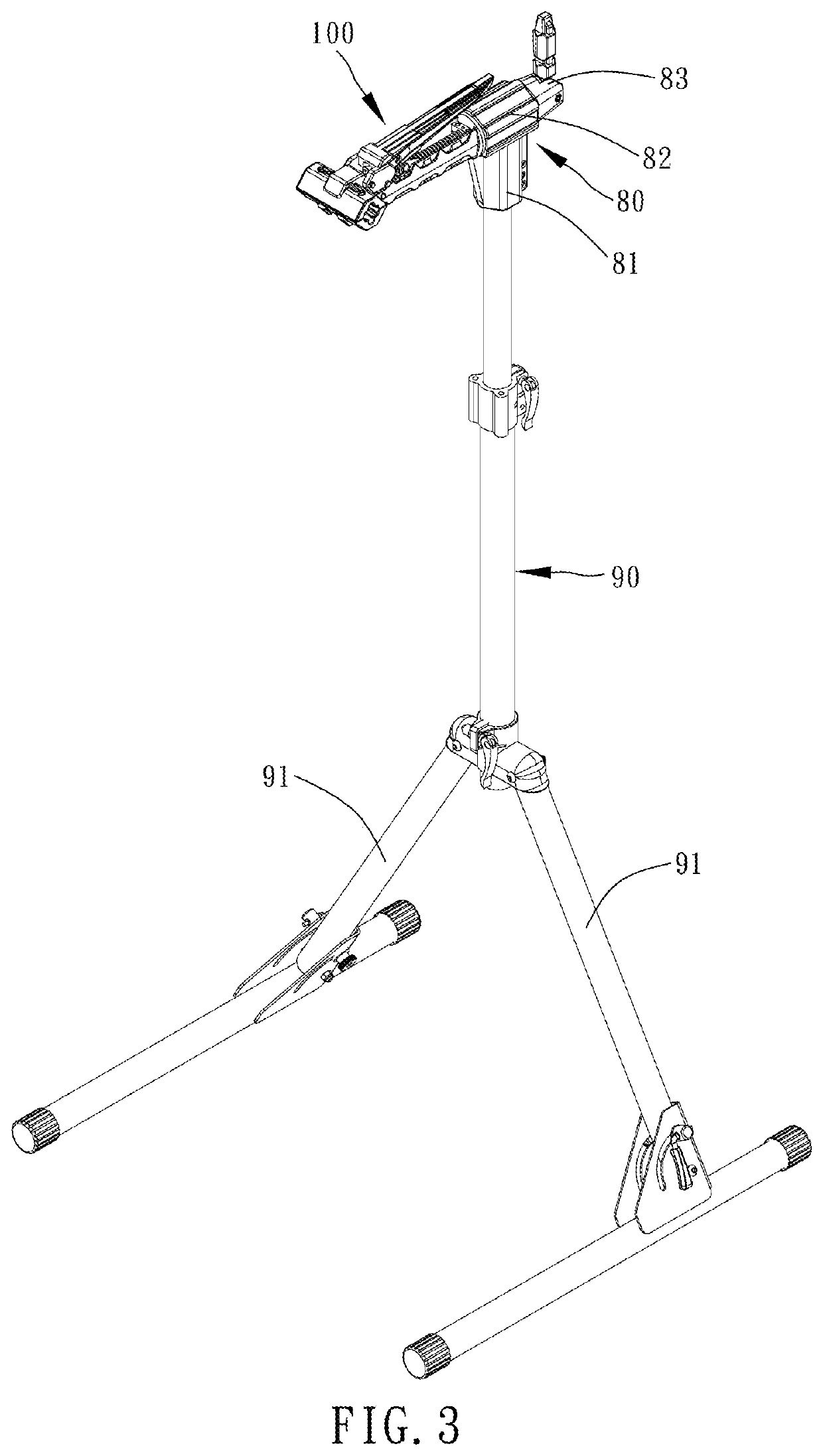
[0017]Referring to FIG. 1 to FIG. 8, a clamp 100 of a bicycle workstand provided by a preferred embodiment of the present invention includes a base 10, an elastic unit 20, an operating arm 30, a link unit 40, and a clamping unit 50.

[0018]The base 10 has an accommodating trough 11 which has an upward opening. Each of two walls of the accommodating trough 11 is provided with a first hole 12. The accommodating trough 11 is provided therein with a protruding stopping portion 13. An end of the base 10 is connected with the clamping unit 50 and another end of the base 10 is connected with a connecting rod 14. The structure and function of the connecting rod 14 will be described below.

[0019]The elastic unit 20 has a shaft 21, a spring 22 and a slide 23. The spring 22 is sleeved onto the shaft 21. The slide 23 is mov...


PUM


Abstract

A clamp of a bicycle workstand includes a base, an elastic unit, an operating arm, a link unit, and a clamping unit. The base has an accommodating trough. The elastic unit has a shaft sleeved with a spring and a slide and disposed in the accommodating trough. The clamping unit has a fixed clamp body disposed on the base, and a movable clamp body pivotably connected with the base and the operating arm. The link unit has a first link and a second link pivotably connected with each other and pivotably connected with the operating arm and the slide respectively. The second link has a cam. Pulling the operating arm can drive the first and second links to swing. The cam is abutted on the shaft and presses it by rolling. The fixed clamp body and the movable clamp body can be coupled for stable clamping.

Description

BACKGROUND OF THE INVENTION1. Field of the Invention[0001]The present invention relates to bicycle supporting frames and more particularly, to a clamp of a bicycle workstand having relatively greater clamping effect.2. Description of the Related Art[0002]Taiwan Patent No. 572001 disclosed a structure of a bicycle workstand including a fixed clamp body, a movable clamp body, an adjusting base, and a controlling rod. The adjusting base is disposed on the fixed clamp body. The controlling rod is inserted through the adjusting base and protrudes out of the fixed clamp body and the movable clamp body. The section of the controlling rod protruding out of the movable clamp body is pivotably attached to a fastening rod. A fastening pressing sheet is sleeved onto the controlling rod and protrudes out of the fixed clamp body. The fastening pressing sheet can limit the axial displacement of the controlling rod, thereby adjusting the open and close condition of the movable clamp body relative t...

Claims


Application Information

Patent Timeline
Patent Type & Authority Patents(United States)
IPC IPC(8): B25B5/10B25B5/04
CPCB25B5/10B25B5/04B25B5/006B25B5/12B25H1/0014
Inventor TSAI, YU-LUNG
Owner JYIN SHENG CO LTD HUATAN TOWNSHIP
Why Eureka
Try Eureka