Acoustic wave device, band pass filter, and multiplexer

a band pass filter and acoustic wave technology, applied in the direction of impedence networks, electrical devices, etc., can solve the problems of degrading the insertion loss of the different band pass filter, the large stop band response, etc., and achieve the effect of reducing or preventing the stop band respons

Active Publication Date: 2021-06-15
MURATA MFG CO LTD
View PDF11 Cites 0 Cited by
  • Summary
  • Abstract
  • Description
  • Claims
  • Application Information

AI Technical Summary

Benefits of technology

[0005]Preferred embodiments of the present invention provide acoustic wave devices and band pass filters which each enable the stop-band response to be reduced or prevented.
[0006]Preferred embodiments of the present invention also provide multiplexers which each enable the stop-band response to be reduced or prevented and in which degradation of insertion loss due to the stop-band response hardly occurs.
[0013]In an acoustic wave device according to a preferred embodiment of the present invention, the sizes, in a transverse direction, of the first electrode fingers, the second electrode fingers, the first offset electrodes, and the second offset electrodes are referred to as widths. The widths of the first electrode fingers and the first offset electrodes in a first area are narrower than the widths of the first electrode fingers in the overlap area. The first area is an area in which the first electrode fingers include the first offset electrodes when viewed in a direction parallel or substantially parallel to a direction in which the second envelope extends. The widths of the second electrode fingers and the second offset electrodes in a second area are narrower than the widths of the second electrode fingers in the overlap area. The second area is an area in which the second electrode fingers include the second offset electrodes when viewed in a direction parallel or substantially parallel to a direction in which the first envelope extends. In this case, degradation of return loss between the resonant frequency and the anti-resonant frequency may be reduced or prevented.
[0014]In an acoustic wave device according to a preferred embodiment of the present invention, the absolute value of an inclination angle of the first offset electrodes and the second offset electrodes is equal to or more than about 5°. The inclination angle is determined relative to the direction orthogonal or substantially orthogonal to the acoustic-wave propagation direction. In this case, the stop-band response may be further reduced or prevented.
[0017]Acoustic wave devices and band pass filters according to preferred embodiments of the present invention may reduce or prevent the stop-band response.

Problems solved by technology

However, in an acoustic wave resonator including an inclined IDT electrode of the related art, the response caused by the upper end of the stop band (an area in which the wave length of acoustic waves is constant because the acoustic waves are confined in a metal grating having a periodic structure), that is, the stop-band response tends to be large.
This may cause the insertion loss of the different band pass filter to be degraded.

Method used


Image

  • Acoustic wave device, band pass filter, and multiplexer
  • Acoustic wave device, band pass filter, and multiplexer
  • Acoustic wave device, band pass filter, and multiplexer

Examples


Embodiment Construction

[0032]The present invention will be clarified below by describing preferred embodiments of the present invention with reference to the drawings.

[0033]It is to be noted that the preferred embodiments described herein are exemplary, and that the configurations of different preferred embodiments may be partially replaced or combined with each other.

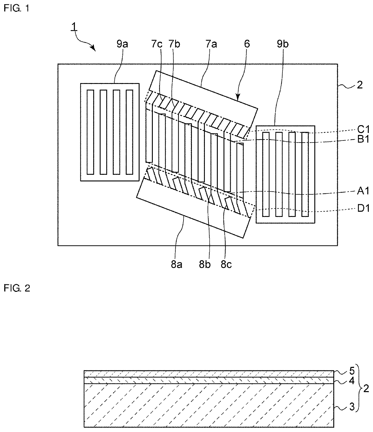
[0034]FIG. 1 is a schematic plan view of an acoustic wave device according to a first preferred embodiment of the present invention. FIG. 2 is a schematic sectional view of a piezoelectric substrate according to the first preferred embodiment.

[0035]As illustrated in FIG. 1, an acoustic wave device 1 includes a piezoelectric substrate 2. As illustrated in FIG. 2, in the present preferred embodiment, the piezoelectric substrate preferably includes a support substrate 3, a low-acoustic-velocity film 4 disposed on the support substrate 3, and a piezoelectric film 5 disposed on the low-acoustic-velocity film 4. The low-acoustic-velocity film 4 is...


PUM


Abstract

An acoustic wave device includes a piezoelectric substrate and an IDT electrode on the piezoelectric substrate. The IDT electrode includes a first busbar and a second busbar that oppose each other, multiple first electrode fingers, multiple second electrode fingers, multiple first offset electrodes, and multiple second offset electrodes. A virtual line connecting the leading ends of the first electrode fingers is referred to as a first envelope. The first envelope is included relative to the acoustic-wave propagation direction. A virtual line connecting the leading ends of the second electrode fingers is referred to as a second envelope. The second envelope is inclined relative to the acoustic-wave propagation direction. The direction in which the first offset electrodes extend and the direction in which the second offset electrodes extend inclined relative to the direction orthogonal or substantially orthogonal to the acoustic-wave propagation direction.

Description

CROSS REFERENCE TO RELATED APPLICATIONS[0001]This application claims the benefit of priority to Japanese Patent Application No. 2017-083373 filed on Apr. 20, 2017 and is a Continuation Application of PCT Application No. PCT / JP2018 / 015234 filed on Apr. 11, 2018. The entire contents of each application are hereby incorporated herein by reference.BACKGROUND OF THE INVENTION1. Field of the Invention[0002]The present invention relates to an acoustic wave device, a band pass filter, and a multiplexer.2 Description of the Related Art[0003]Heretofore, acoustic wave devices have been widely used, for example, in filters in cellular phones. Japanese Unexamined Patent Application Publication No. 2000-286663 describes an acoustic wave resonator including an inclined IDT electrode in which the busbars incline relative to the acoustic-wave propagation direction. The busbars which are inclined as described above cause suppression of spurious responses produced due to the transverse mode.[0004]Howe...

Claims


Application Information

Patent Timeline
Patent Type & Authority Patents(United States)
IPC IPC(8): H03H9/145H03H9/02H03H9/205H03H9/54H03H9/70
CPCH03H9/145H03H9/02007H03H9/205H03H9/54H03H9/706H03H9/14547H03H9/14558H03H9/02574H03H9/14573
Inventor DAIMON, KATSUYA
Owner MURATA MFG CO LTD
Why Eureka
Try Eureka