Timepiece with rotatable crown having tactile feel

a technology of rotatable crown and timepiece, which is applied in the direction of normal winding, instruments, and horology, can solve the problems of shaft portion sliding, no operational “feel,” and increase in the number of components and cost compared with the conventional common timepiece, and achieve the effect of suppressing inadvertent rotation of the crown and simple structur

Active Publication Date: 2021-06-22
SEIKO INSTR INC
View PDF7 Cites 8 Cited by
  • Summary
  • Abstract
  • Description
  • Claims
  • Application Information

AI Technical Summary

Benefits of technology

[0007]Each of embodiments of the present invention has been made in view of the above problems. Each of embodiments provides a timepiece which provides a tactile feel in a simple structure and which can suppress inadvertent rotation of a crown.

Problems solved by technology

No operational “feel,” however, is experienced when rotating the driving crown.
In the rotation operating device of the prior art document, however, it is necessary to provide the spring member for pressing the protrusions and recesses of the movable cogwheel against the protrusions and recesses of the stationary cogwheel, resulting in an increase in the number of components and in cost compared with the conventional common timepiece.
Further, in the rotation operating device of the prior art document, there exists, between an insertion hole of the movable cogwheel and the shaft portion of the driving crown inserted into this insertion hole, a gap for causing the shaft portion to slide.

Method used


Image

  • Timepiece with rotatable crown having tactile feel
  • Timepiece with rotatable crown having tactile feel
  • Timepiece with rotatable crown having tactile feel

Examples


first embodiment

[0024]The first embodiment of the present invention will be described with reference to FIGS. 1 through 6.

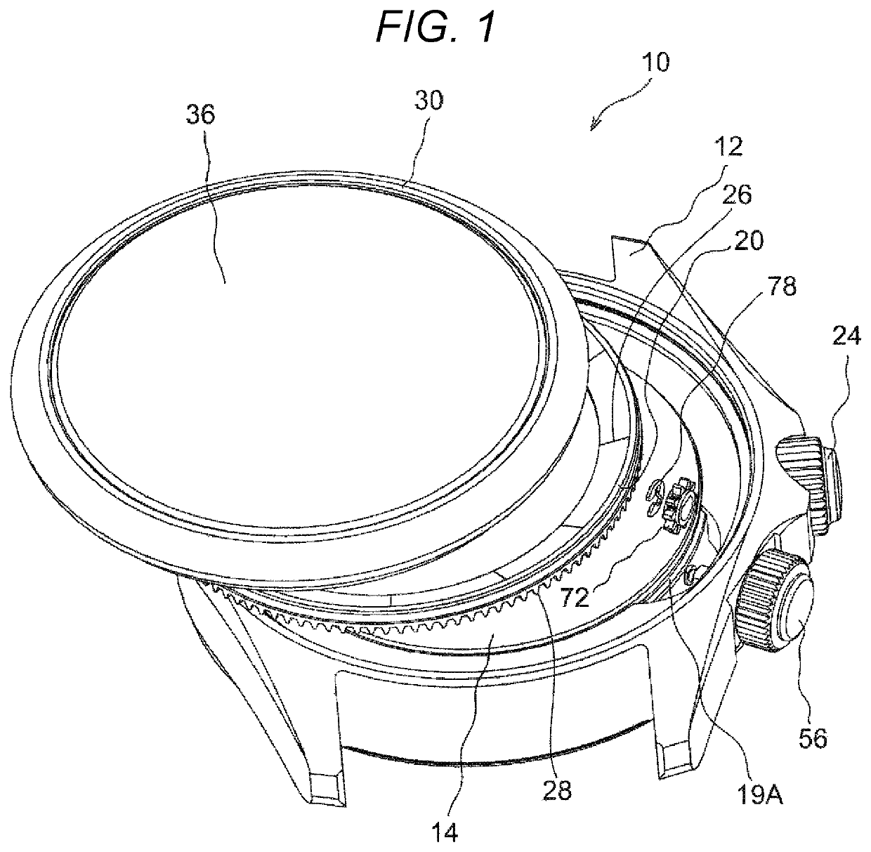
[0025]As shown in FIGS. 1 and 2, a wristwatch 10 is equipped with a case 12 constituting an outer jacket. The belt of the wristwatch 10 is omitted in the drawing.

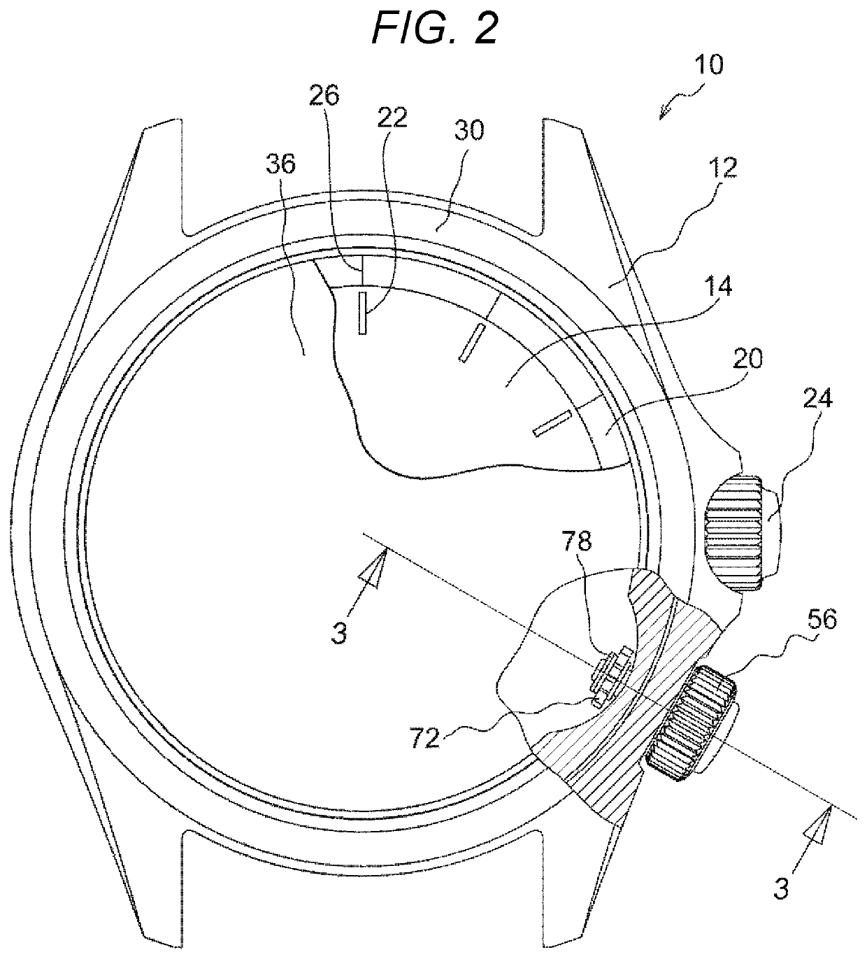
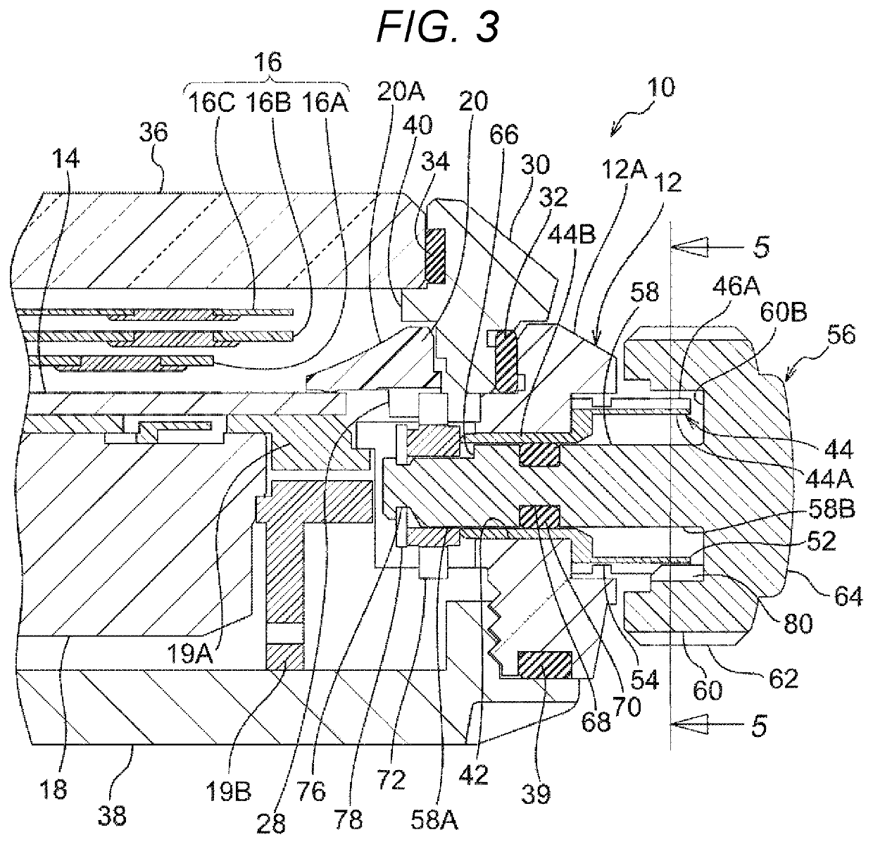
[0026]As shown in FIGS. 2 and 3, accommodated in the case 12 are mechanisms such as a dial 14, a movement 18 controlling the movement of time indicator hands 16 indicating time, and a rotated member, for example, an in-revolving ring 20. The movement 18 is accommodated in the case 12 along with a movement retaining ring 19A and a middle frame 19B. The rotated member is not restricted to the in-revolving ring 20 described below. It is only necessary for the rotated member to be one that is rotatably accommodated in the case 12 and that is rotated in conjunction with an operation performed from the outside of the case 12.

[0027]As shown in FIG. 2, the dial 14 is circular and has in the peripheral portion a time-indicating ...

second embodiment

[0069]The wristwatch 10 according to the second embodiment of the present invention will be described with reference to FIGS. 7 through 10. The components that are the same as those of the first embodiment are indicated by the same reference numerals, and a description thereof will be left out.

[0070]As shown in FIG. 7, in the wristwatch 10 of the present embodiment, an elastic material winding stem pipe 82 of a configuration different from that of the first embodiment is inserted into the through-hole 42 of the case 12. As shown in FIGS. 7 through 9, the elastic material winding stem pipe 82 of the present embodiment is equipped, on one side of a small diameter portion 82B formed as a cylinder, with a large diameter portion 82A formed as a tube of a hexagonal sectional configuration. The large diameter portion 82A has, at every other one of six corner portions, expanding slots 84 extending in the axial direction. The expanding slots 84 are formed to extend from the end portion of th...

third embodiment

[0089]The wristwatch 10 according the third embodiment of the present invention will be described with reference to FIG. 11. The components that are the same as those of the above-described embodiments are indicated by the same reference numerals, and a description thereof will be left out.

[0090]As shown in FIG. 11, the wristwatch 10 of the present embodiment is a modification of the second embodiment, and the configuration of the elastic material winding stem pipe 82 is somewhat different from that of the second embodiment.

[0091]The large diameter portion 82A of the elastic material winding stem pipe 82 of the present embodiment is of a cylindrical configuration, and has on the inner peripheral surface thereof a protrusion 108 configured to enter the trough portion 106 between the teeth 104A of the shaft member 92. The operation and effect of the present embodiment is the same as those of the second embodiment.

Other Embodiments

[0092]The above description of the embodiment of the pr...


PUM


Abstract

A timepiece which provides a tactile feel in a simple structure and which can suppress inadvertent rotation of a driving crown is to be provided. A wristwatch includes an elastic material winding stem pipe protruding on the outer side of a case and a distal end portion of which is capable of elastic deformation in a radial direction; a shaft member of a driving crown rotatably inserted into the elastic material winding stem pipe; protrusions formed on the peripheral surface of the driving crown; and trough portions formed in the peripheral surface of the elastic material winding stem pipe and configured to be engaged with the protrusions.

Description

RELATED APPLICATIONS[0001]This application claims priority under 35 U.S.C. § 119 to Japanese Patent Application No. 2018-039913 filed on Mar. 6, 2018, the entire content of which is hereby incorporated by reference.BACKGROUND OF THE INVENTION1. Field of the Invention[0002]The present disclosure relates to the structure of a timepiece.2. Description of the Related Art[0003]For example, in a conventional common timepiece equipped with an in-revolving ring, it is possible to hold an in-revolving cogwheel installed on the shaft of a driving crown and a cogwheel formed on the in-revolving ring in mesh with each other, and to freely determine the rotational position of the in-revolving ring through rotation of the driving crown. No operational “feel,” however, is experienced when rotating the driving crown. That is, the rotational position of the driving crown, i.e., the rotational position of the in-revolving ring, is maintained solely by the resistance of a packing in the driving crown ...

Claims


Application Information

Patent Timeline
Patent Type & Authority Patents(United States)
IPC IPC(8): G04B3/04
CPCG04B3/041G04B3/043G04B37/06G04B19/28G04B19/286
Inventor IGUCHI, KATSUNOBU
Owner SEIKO INSTR INC
Why Eureka
Try Eureka