Variable damping force damper

a damper and variable technology, applied in the direction of shock absorbers, mechanical equipment, transportation and packaging, etc., can solve the problems of reducing the mechanical strength of the piston main body, affecting the smoothness of the telescopic, so as to reduce the number of assembly steps, prevent the deformation of the electric coil, and reduce the number of components

Active Publication Date: 2016-05-03
HONDA MOTOR CO LTD
View PDF13 Cites 3 Cited by
  • Summary
  • Abstract
  • Description
  • Claims
  • Application Information

AI Technical Summary

Benefits of technology

[0015]According to the present invention, since the outer yoke and the inner yoke are connected with each other by the metallic connection means, the electromagnetic coil is prevented from deforming easily even when the piston is strongly pressed against the inner wall surface of the cylinder. Thus, displacement between the axis of the cylinder and the axis of the piston is restrained, wear of the seal is suppressed, and wire break or the like in the electromagnetic coil becomes less likely to occur. In the structure in which the piston is provided with a pair of communication oil passages, one having an opening in one axial end and the other having an opening in an opposite axial end, and the valve plate is provided to each of the openings of the pair of communication oil passages, damping forces on the expansion side and the contraction side can be variably controlled by a single electromagnetic coil. In the structure in which the electromagnetic coil is offset toward one of the valve plates relative to an axially middle position between the valve plates, it is possible, for example, to make the damping force on the expansion side larger than the damping force on the contraction side. In the structure in which the connection means consists of a connection member made of a ferromagnetic material integrally with the inner yoke and the outer yoke, the number of components and the number of assembly steps can be reduced. In the structure in which the connection member is configured to have an axial size smaller than a thickness of the valve plate, the magnetic flux flowing through the connection member is reduced, and thus, a relatively large magnetic force can be obtained on each side of the electromagnetic coil. In the structure in which the connection means consists of a connection member made of a non-magnetic material, magnetic flux does not flow through the connection member, and thus, it is possible to increase the axial size of the connection member, thereby restraining relative displacement between the inner yoke and the outer yoke more effectively. Further, in the structure in which the connection means is disposed at a position spaced from the piston ring in an axial direction, bending, rotation and twisting of the piston can be suppressed effectively.DETAILED DESCRIPTION OF THE PREFERRED EMBODIMENT(S)
[0016]In the following, detailed description will be made of an exemplary embodiment, in which the present invention is applied to a mono-tube variable damping force damper constituting a front suspension of an automobile, with reference to the drawings. It is to be noted that with regard to the members and positional relationships in the exemplary embodiment, description will be made on the assumption that the upward direction in FIG. 2 indicates the “upward” direction.<<Structure of the Exemplary Embodiment>><Suspension>
[0017]As shown in FIG. 1, a front suspension 1 in the exemplary embodiment is of a so-called McPherson strut type, and includes, as main components thereof, a steering knuckle 3 (wheel-side member) rotatably supporting a wheel 2, a strut damper (hereinafter, simply referred to as a damper) 5 having upper and lower ends connected with a damper mount 4 (vehicle body-side member) and the steering knuckle 3, respectively, a lower arm 7 having left and right ends connected with a suspension member 6 and the steering knuckle 3, respectively, and spring 8 fitted over an upper part of the damper 5.<Damper>
[0018]As shown in FIG. 2, the damper 5 in the exemplary embodiment is of a mono-tube type (De Carbon type), and includes a hollow cylinder 12 filled with hydraulic oil and having a lower portion connected with the steering knuckle 3, a piston rod 13 having an upper end connected with the damper mount 4 and being slidable relative to the cylinder 12 in an axial direction, a piston 16 mounted at an end of the piston rod 13 and separating the interior of the cylinder 12 into a rod-side oil chamber 14 and a piston-side oil chamber 15, a free piston 18 defining a high pressure gas chamber 17 in a lower part of the cylinder 12, a cover 19 for preventing adhesion of dust to the piston rod 13 and the like, a bump stop 20 for exerting a cushioning effect at full bounce, and a seal 21 slidably supporting the piston rod 13 at a top end of the cylinder 12. An upper spring seat 22, with which the upper end of the spring 8 is in pressed contact, is fixedly attached to the upper part of the cover 19, while a lower spring seat 23, with which the lower end of the spring 8 is in pressed contact, is fixedly attached to a vertically middle part of the cylinder 12.<Piston>
[0019]With additional reference to FIGS. 3 and 4, the piston 16 is constituted of a piston main body 30, an expansion-side valve plate 41, a contraction-side valve plate 42, an electromagnetic coil 43, a bolt with a hexagonal hole (hereinafter, simply referred to as a bolt) 44, and a piston ring 45.
[0020]The piston main body 30 is an integrally formed component made of a ferromagnetic material such as a ferrite-based material by means of powder metallurgy, die casting or the like, and includes a hollow cylindrical outer yoke 31 that is coaxial with the cylinder 12, a columnar inner yoke 34 having the same axial length as that of the outer yoke 31 and disposed coaxially with the outer yoke 31 such that an outer peripheral surface of the inner yoke 34 opposes an inner peripheral surface of the outer yoke 31 via a first gap 32 and a second gap 33, and an annular connection member 35 that connects the outer yoke 31 and the inner yoke 34 with each other at an axially middle part of the piston 16 and separates the first and second gaps 32 and 33 from each other. The inner yoke 34 includes upper and lower portions having respective female threaded bores 36, 37 formed on the axis thereof such that a male threaded portion 13a of the piston rod 13 and the bolt 44 are threadably engaged with the bores 36, 37, respectively. Further, the inner yoke 34 is formed with an expansion-side communication oil passage 38 and a contraction-side communication oil passage 39, each extending through the inner yoke 34 in the axial direction. Similarly to a piston of an internal combustion engine, the piston ring 45 consists of an annular member having an end gap (not shown in the drawings), and is fitted in a retaining groove 40 formed in a lower part of the outer yoke 31 such that the piston ring 45 is in slidable contact with the inner peripheral surface of the cylinder 12.

Problems solved by technology

In the variable damping force dampers disclosed in Patent Documents 1 and 2, since the electromagnetic coil is disposed between the inner yoke and the outer yoke, the mechanical strength of the piston main body is reduced, and this may cause the following problems.
This may cause deformation of the electromagnetic coil, such that the axis of the outer yoke is offset from the axis of the inner yoke, resulting in a slight misalignment between the axis of the cylinder and the axis of the piston main body.
This may hinder a smooth telescopic action of the damper and cause a seal, which is provided in a cylinder end portion such that the piston rod is in slidable contact therewith, to be worn out in a relatively short period of time.

Method used


Image

  • Variable damping force damper
  • Variable damping force damper
  • Variable damping force damper

Examples


first modified embodiment

[0038]FIG. 6 is an enlarged fragmentary cross-sectional view showing a first modified embodiment;

second modified embodiment

[0039]FIG. 7 is an enlarged fragmentary cross-sectional view showing a second modified embodiment;

third modified embodiment

[0040]FIG. 8 is an enlarged fragmentary cross-sectional view showing a third modified embodiment;


PUM


Abstract

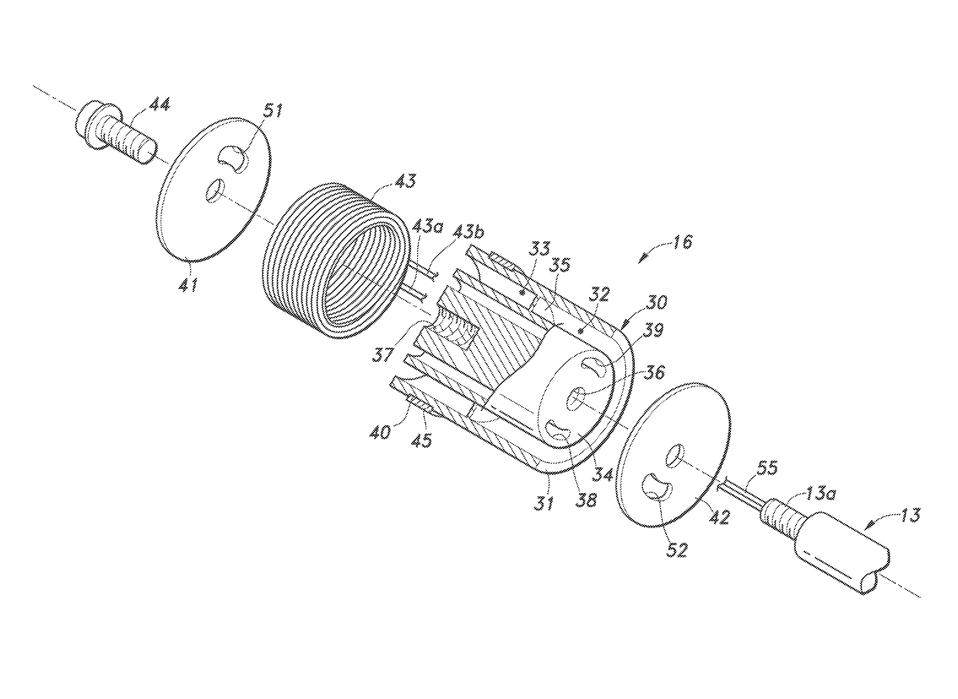
Provided is a solenoid-type variable damping force damper that improves the strength of the piston and prevents wire break in the electromagnetic coil. A piston includes a piston main body, an expansion-side valve plate, a contraction-side valve plate, an electromagnetic coil, and a bolt. The piston main body is an integrally formed component made of a ferromagnetic material, and includes a hollow cylindrical outer yoke that is in slidable contact with an inner peripheral surface of a cylinder, a columnar inner yoke having an outer peripheral surface opposing an inner peripheral surface of the outer yoke via first and second gaps, and a connection member connecting the outer yoke and the inner yoke with each other at an axially middle position of the piston and separating the first and second gaps from each other. The electromagnetic coil is fitted in the second gap of the piston main body.

Description

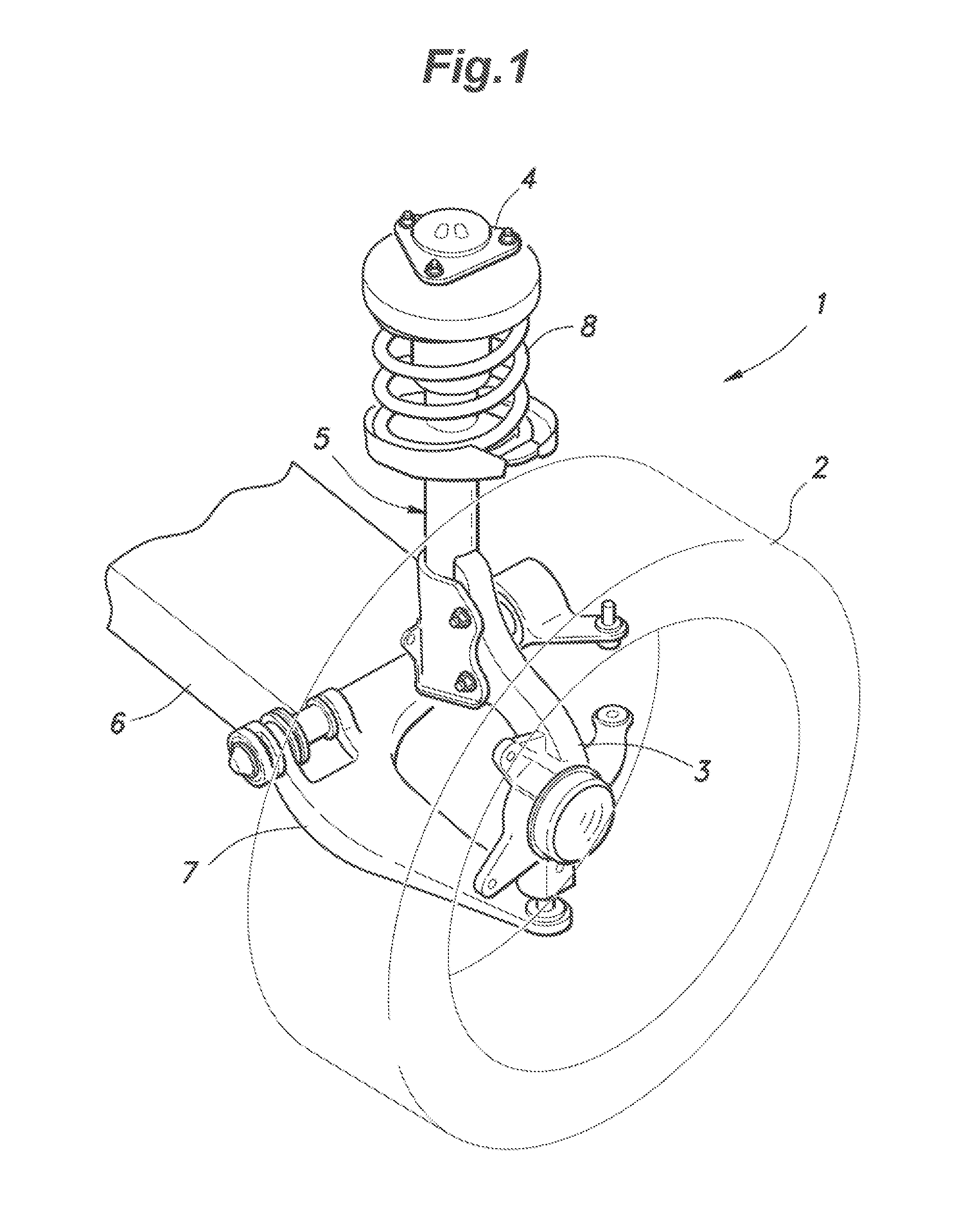
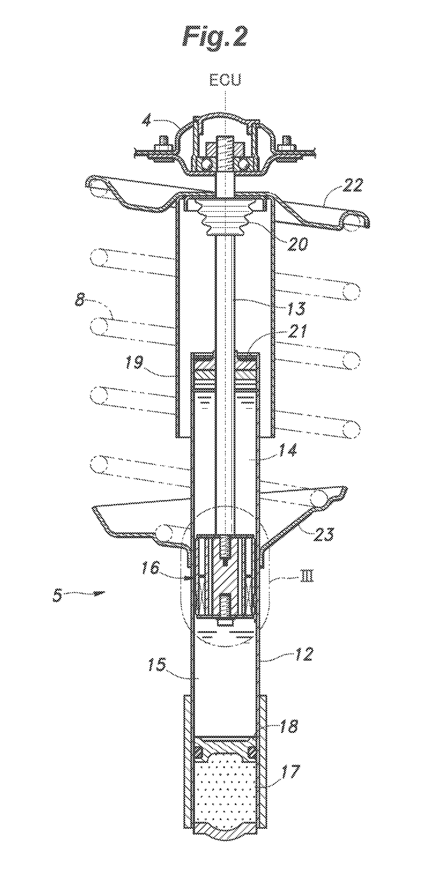
TECHNICAL FIELD[0001]The present invention relates to a solenoid-type variable damping force damper for use in a suspension of an automobile, and particularly relates to technology for improving the strength of a piston and preventing wire break in an electromagnetic coil.BACKGROUND OF THE INVENTION[0002]A suspension is an important element that significantly affects the driving stability of an automobile, and typically includes, as main components thereof, a link (such as an arm, rod, etc.) that supports a wheel to be movable vertically relative to a vehicle body, a spring that is flexible to absorb impact from a road surface or the like, and a damper for damping the oscillation of the spring. Such a damper for an automotive suspension is typically embodied as a tubular damper which includes a hollow cylinder filled with hydraulic oil, a piston configured to slide in the cylinder in an axial direction, and a piston rod having an end connected with the piston, where the hydraulic oi...

Claims


Application Information

Patent Timeline
Patent Type & Authority Patents(United States)
IPC IPC(8): F16F9/44F16F9/348B60G17/08F16F9/53F16F9/22
CPCF16F9/22F16F9/535F16F9/3484B60G17/08
Inventor NAKAJIMA, KIYOSHI
Owner HONDA MOTOR CO LTD
Why Eureka
Try Eureka