Image processing device and image processing method
a technology of image processing and image, applied in the field of image processing device, image processing method, program, etc., can solve the problems of distorted captured image and inability to accurately measure distan
- Summary
- Abstract
- Description
- Claims
- Application Information
AI Technical Summary
Benefits of technology
Problems solved by technology
Method used
Image


Examples
first embodiment
1. First Embodiment
[0054]
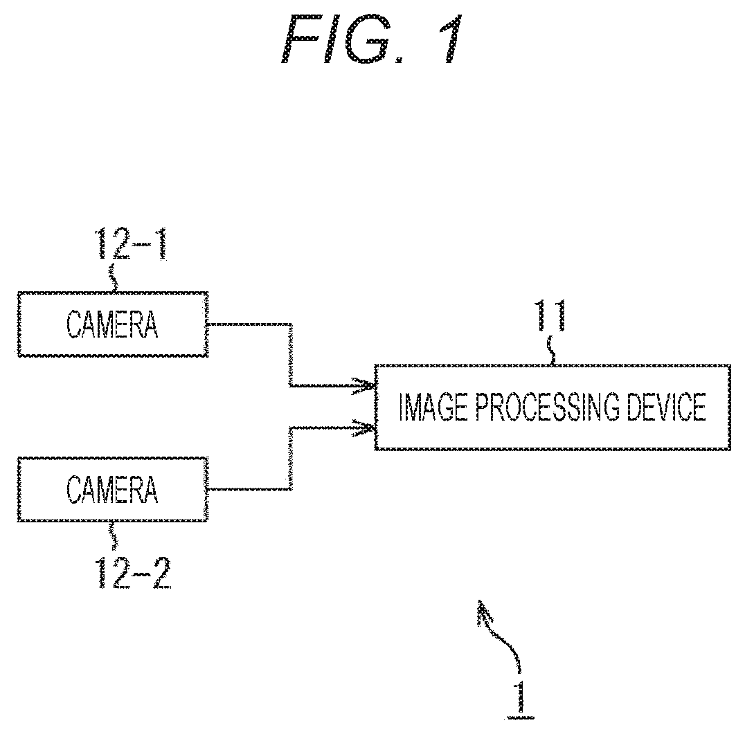
[0055]FIG. 1 is a block diagram illustrating a configuration example of a stereo camera system according to an embodiment of the present technology.
[0056]A stereo camera system 1 illustrated in FIG. 1 is configured by connecting a camera 12-1 and a camera 12-2 constituting a stereo camera to an image processing device 11.
[0057]The camera 12-1 and the camera 12-2 are fixed with optical axes in the same direction in a horizontal direction or a vertical direction with a predetermined interval, and are provided with lenses having the same viewing angle.
[0058]The camera 12-1 and the camera 12-2 capture images at the same timing and output the captured images. The image captured by the camera 12-1 and the image captured by the camera 12-2 are input to the image processing device 11 as a stereo image. The stereo image input to the image processing device 11 is used to calculate a distance to an object reflected in the stereo image.
[0059]FIG. 2 is a diagram illustra...
second embodiment
2. Second Embodiment
[0193]In the optical axis correction performed as the first stage processing of the rectification as described above, the processing that may cause the largest error is the detection (estimation) of the optical axis. If the detection of the optical axis has an error and the corrected optical axis cannot be set with high accuracy, the amount of correction in the projective transformation performed as the second stage processing becomes large and there is a possibility that the distortion cannot be corrected.
[0194]Here, another processing by an image processing device 11 for generating a parallelization parameter will be described with reference to the flowchart in FIG. 18. The optical axis correction performed as the first stage processing is performed in a form different from the processing described with reference to FIG. 16.
[0195]The processing in FIG. 18 is similar to the processing described with reference to FIG. 16, except that evaluation of a correction re...
third embodiment
3. Third Embodiment
[0213]Cameras 12-1 and 12-2, which are fisheye cameras, can capture a wide range. Therefore, there are some cases where a housing to which a stereo camera system 1 is attached is reflected, depending on how the stereo camera system 1 is attached.
[0214]For example, in a stereo image in FIG. 2, a vehicle body C of an automobile is reflected as described above. In a case of projecting such a stereo image onto a virtual spherical surface and reprojecting a projected image onto a plurality of planes, the vehicle body C is reflected in each of planar images. Here, when the above-described rectification is performed, the distance to the vehicle body C can be calculated.
[0215]When using the stereo camera system 1 that has completed the rectification, distance measurement may not be correctly performed due to distortion due to impact, heat, aging, or the like. In this case, such a problem is solved by performing rectification again.
[0216]However, in the rectification befor...
PUM
 Abstract
Description
Claims
Application Information