Multiple torques inertial thruster engine and methodology

a multi-torque inertial thruster and engine technology, applied in the direction of motors, machines/engines, mechanical apparatuses, etc., can solve the problems of not being able to withstand experimental rigor, the prior art dealing with inertial thrusters does not adequately address, and the popular conception of the word “action” is often poorly defined and therefore misunderstood. , to achieve the effect of reducing the impact of the connecting arm, minimizing or eliminating such

Active Publication Date: 2021-06-29
ABERS MARK DAVID
View PDF8 Cites 0 Cited by
  • Summary
  • Abstract
  • Description
  • Claims
  • Application Information

AI Technical Summary

Benefits of technology

[0021]An additional discovery is that the thrust of phase 2 is enhanced when the equipment is configured to accelerate the connecting arms 29 along with the attached rotors 14. This is in contradistinction to phase 1 (minimized-thrust phase) where constant speed and no acceleration is desirable. I also discovered that thrust can be improved upon during phase 2 by immobilizing the rotation of the central axle 28&36. This impedance of the central axle 28&36 immediately negates gyroscopic effects and enhances the return of the precessable mass 14 to the start position.
[0029]Previous art does not a disclose credible design for a rotary inertial thrust. This disclose describes two such devices: the Radius MUTINT 154 and the Tangent MUTINT 155. A rotary device improves the overall smoothness and efficiency of operation besides broadening the base for the types of methods that can be used. Other improvements over prior art in this invention include design simplification and critical weight reduction that accommodates the above modifications.

Problems solved by technology

The popular conception of the word “action” is often poorly defined and therefore misunderstood.
Especially Fiala's design demonstrated great ingenuity, however it was premised on an at least one faulty assumption.
Said assertion does not withstand experimental rigor.
The problem is that the prior art dealing with inertial thrusters does not adequately address the crucial issue of strategic damping 200.
Prior art attempts at inertial thrust do not adequately describe either a device and / or a method to appropriately incorporate the aforementioned requirements.

Method used


Image

  • Multiple torques inertial thruster engine and methodology
  • Multiple torques inertial thruster engine and methodology
  • Multiple torques inertial thruster engine and methodology

Examples


Embodiment Construction

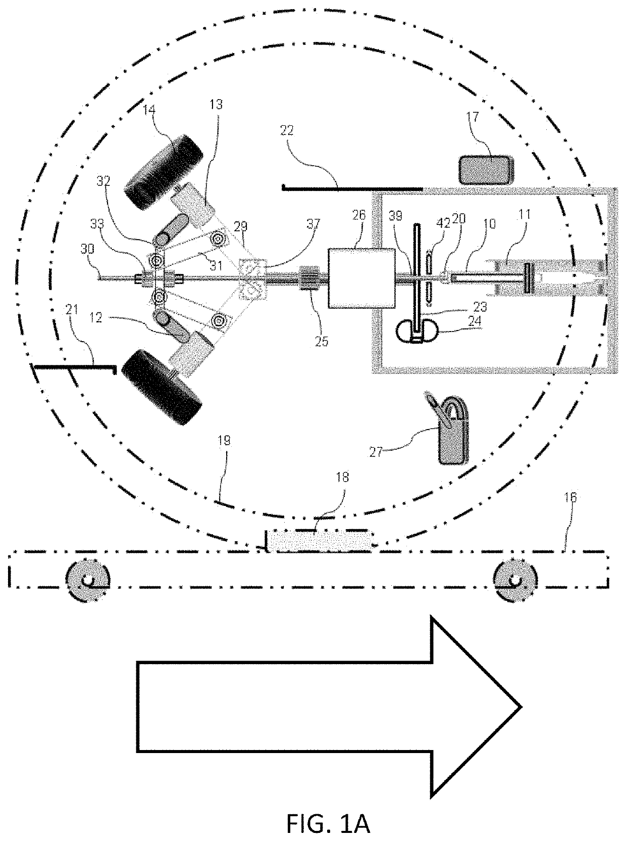
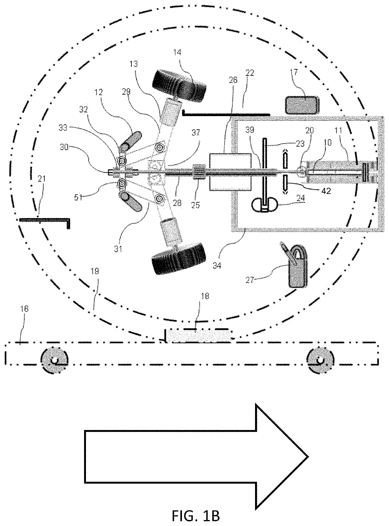
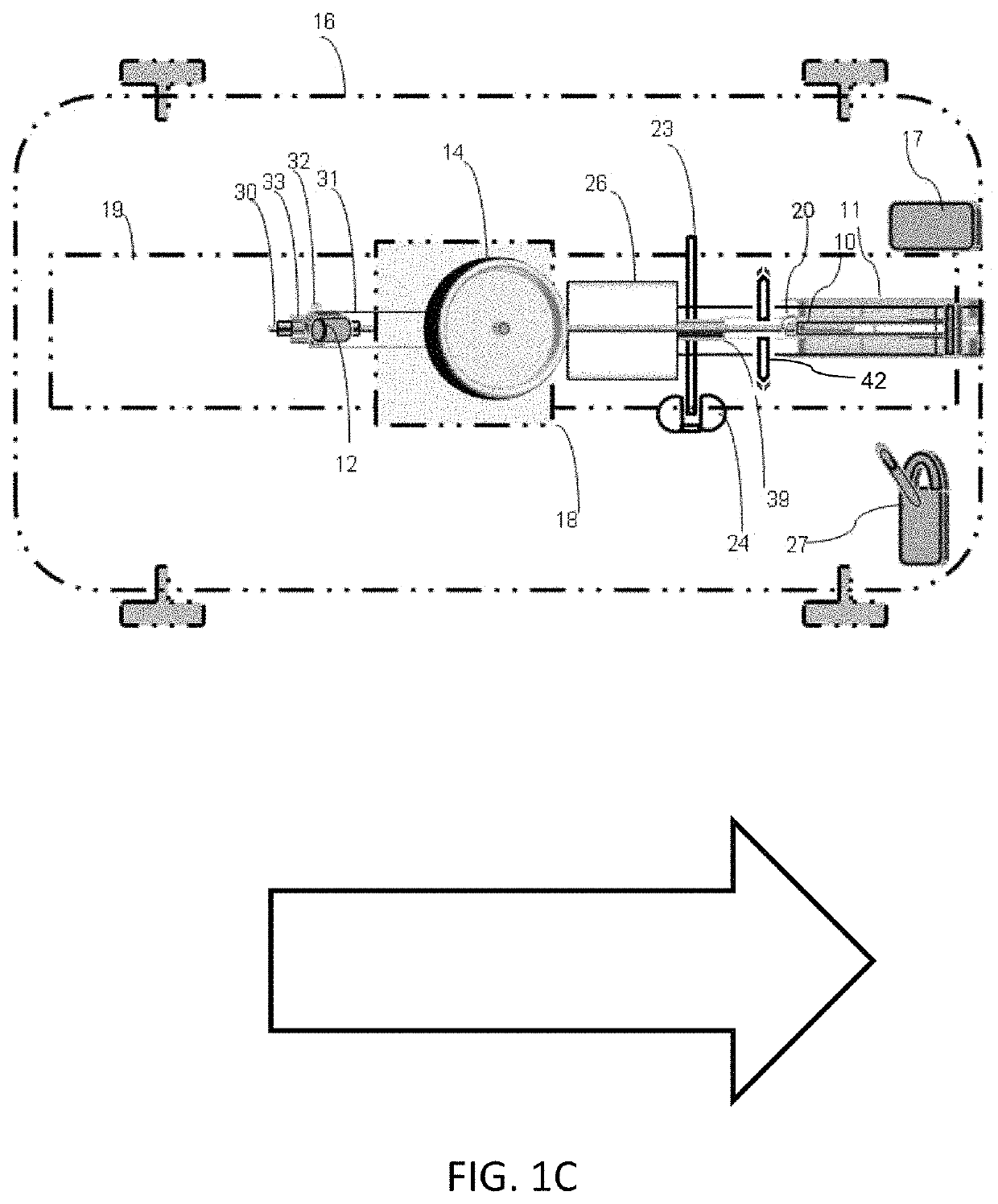
[0051]While this invention is susceptible to embodiments in many different forms, there is shown in the drawings and will herein be described in detail specific embodiments, with the under standing that the present disclosure of such embodiments is to be considered as an example of the principles and not intended to limit the invention to the specific embodiments shown and described. In the description below, like reference numerals are used to describe the same, similar or corresponding parts in several views of the drawings. This description describes embodiments in order for those skilled in the art to practice the invention. The glossary (in the end portion of the specification section) defines the meaning of terms used herein.

[0052]In FIGS. 1A through 2C we have the Pivot MUTINT 151 and the Flex MUTINT 152 embodiments. In said embodiments, a variable-speed, non-geared, hollow-shaft motor 26 is mounted onto a rotatable frame 19. Said variable-speed motor 1 will be referred to as...


PUM


Abstract

This invention discloses an inertial-thruster architecture wherein active and passive damping techniques result in the redirection, absorption, neutralization, and / or enhancement of the effect of torque-induced precession on both oscillatory and rotary devices. These novel mechanical and methodological embodiments demonstrate that the redirection of precession during the appropriate phase of operations will achieve the objective of rectilinear movement when combined with the displacement of one or more precessable masses.

Description

CROSS REFERENCED TO RELATED APPLICATIONS[0001]This application claims priority to U.S. Provisional patent application No. 62 / 481,270, (titled “Multiple Torques Inertial Thruster Engine (MUTINTE)”, filed on Apr. 4, 2017 which is incorporated by reference herein, in its entirety and for all purposes.[0002]Notice to File Missing Parts: This substitute specification contains no new matter that affects the scope or nature of the invention as disclosed in the original patent application. / Mark David Abers / Today's Date: 2018 Jun. 1.[0003]If there are any contradictions or inconsistencies in language between this application and one or more of the cases that have been incorporated by reference that might affect the interpretation of the claims in this case, the claims in this case should be interpreted to be consistent with the language in this case.FEDERALLY SPONSORED RESEARCH[0004]Not Applicable.SEQUENCE LISTING[0005]Not Applicable.RELATED APPLICATION DATA[0006]Int. Cl: B64G1 / 28; F03G3 / 08...

Claims


Application Information

Patent Timeline
Patent Type & Authority Patents(United States)
IPC IPC(8): F03G3/08
CPCF03G3/08F03G7/125
Inventor ABERS, MARK DAVID
Owner ABERS MARK DAVID
Why Eureka
Try Eureka