Intramedullary rod fixation system

Active Publication Date: 2015-03-12
ROGACHEFSKY RICHARD A
View PDF3 Cites 6 Cited by
  • Summary
  • Abstract
  • Description
  • Claims
  • Application Information

AI Technical Summary

Benefits of technology

[0037]The invention is advantageous with regard to conventional use of plates and screws as the rod and screws will be placed with-in the bone so that tendon adherence does not occur. Also the rod and screws may be placed through small incisions percutaneously, minimizing trauma to the soft tissues, and tendons. Immediate stable internal fi

Problems solved by technology

The hand is one of the most intricate and complex structures of the human body.
Any disruption to the anatomic structures can cause profound loss of function and disability to not only the hand, but the patient as a whole.
If the skeletal system or the highly intricate soft tissue structures are disrupted the function of the hand is compromised.
The most common cause of hand fractures is due to trauma.
More severe fractures that occur, such as unstable fractures, comminuted fractures or open fractures of the hand, are more problematic to treat.
Many times conservative cast or splint treatment does not provide enough stability to the fracture and the fracture heals in a mal-united or angled position.
This causes loss of function of the hand.
The disadvantage of open reduction and internal fixation is the disruption of the soft tissues and especially the extensor mechanism during surgical dissection.
This compromises tendon function and ultimately hand function.
Fractures and injury that occur in these regions either by trauma or surgery lead to a high incidence of tendon adherence and loss of finger mot

Method used


Image

  • Intramedullary rod fixation system
  • Intramedullary rod fixation system
  • Intramedullary rod fixation system

Examples


Example

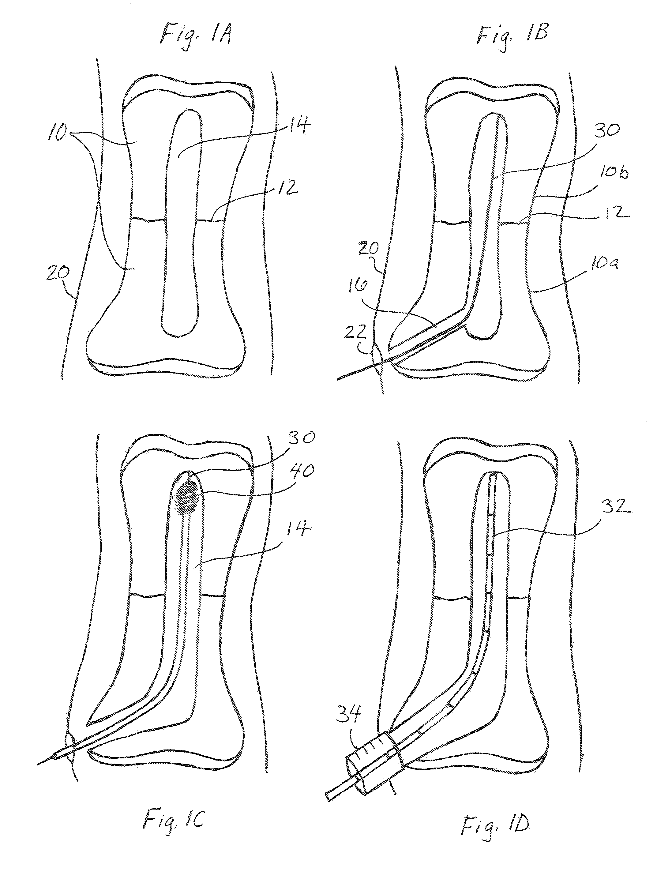
[0043]As shown in FIG. 1A, the technique for fixation of a fracture 12 in a bone 10 would be to first correct the fracture alignment by indirect reduction. Then a small incision 22 as shown in FIG. 1B would be made through the skin 20 and extensor tendon (not shown) down to the bone at the base of the bone. The base of the proximal phalanx would be used for fixation of a proximal phalanx fracture and the base of the middle phalanx would be used for fixation of a middle phalanx fracture. In one embodiment, an awl would be used to make an opening 16 in the base of the bone. The location of the awl and correct entrance into the bone would be verified under fluoroscopic x ray. Alternatively, the opening 16 in the base of the bone could be made with a drill and soft tissue guide. Then, as shown in FIG. 1B, a guide wire 30 would be placed through the opening 16, into the intramedullary canal 14 of the proximal fragment 10a, across the fracture 12 and into the intramedullary canal of the d...


PUM


Abstract

A method for fixation of a fracture of a bone having an intramedullary canal. An intramedullary rod is inserted into the intramedullary canal of the bone, wherein the intramedullary rod includes at least one proximal hole and at least one distal hole. Proximal and distal screws or pegs are inserted through the bone and through the proximal and distal holes in the rod, wherein the proximal and the distal screws or pegs are headless screws or pegs and are selected to have a size and are inserted through the proximal and distal holes in the rod such that the screws or pegs do not extend substantially beyond an exterior surface of the bone. Further described are apparatus and a kit for intramedullary fixation of fractures of bones of the hand. The methods, apparatus and kits of the invention are advantageously designed for percutaneous placement of intramedullary rods into the intramedullary canal of metacarpal or phalanx bones of the hand to stabilize fractures, and in particular in the proximal or middle phalanx bones of the hand. Rotational control is provided by locking screws or pegs through the rod, also placed percutaneously. Specific alignment jigs, drills, screw drivers and equipment may be used for placement of the rod and screws, wherein the rod and screws will stabilize the fracture.

Description

FIELD OF THE INVENTION[0001]This invention relates generally to intramedullary rod fixation systems. More specifically, this invention relates to an intramedullary rod fixation system employing intramedullary rods and locking screws or pegs especially useful for surgical treatment of fractures of bones of the hand.BACKGROUND OF THE INVENTION[0002]The hand is one of the most intricate and complex structures of the human body. It is a complex structure made of bone and soft tissue. The structures work in a precise and extremely well coordinated way to produce well coordinated and precise movements. The hand can perform a wide variety of function and is capable of both strength and power or fine motor and sensory function. Any disruption to the anatomic structures can cause profound loss of function and disability to not only the hand, but the patient as a whole. The hand performs range of motion, strength and fine motor skills such as pinch.[0003]The bones of the hand provide the scaf...

Claims


Application Information

Patent Timeline
IPC IPC(8): A61B17/72A61B17/86
CPCA61B17/8645A61B17/7291A61B17/164A61B17/1725A61B17/7208A61B17/725A61B17/863A61B2017/564
Inventor ROGACHEFSKY, RICHARD A.
Owner ROGACHEFSKY RICHARD A
Why Eureka
Try Eureka