Displacement detector device

a technology of displacement detector and detector device, which is applied in the direction of special purpose recording/indication apparatus, magnetic sensor geometrical arrangement, instruments, etc., can solve the problem of not being able to address specific correction methods, and achieve the effect of reducing or preventing detection errors of displacement detector devi

Active Publication Date: 2021-06-29
MURATA MFG CO LTD
View PDF20 Cites 0 Cited by
  • Summary
  • Abstract
  • Description
  • Claims
  • Application Information

AI Technical Summary

Benefits of technology

[0010]Preferred embodiments of the present invention provide displacement detector devices that are each able to significantly reduce or prevent detection errors caused by variations in the temperature characteristics of multiple magnetic sensors.
[0020]According to preferred embodiments of the present invention, it is possible to significantly reduce or prevent detection errors of a displacement detector device caused by variations in the temperature characteristics of multiple magnetic sensors.

Problems solved by technology

However, a specific correction method is not addressed in Japanese Unexamined Patent Application Publication No. 2002-22403.

Method used


Image

  • Displacement detector device
  • Displacement detector device
  • Displacement detector device

Examples


Embodiment Construction

lass="d_n">[0041]Displacement detector device according to preferred embodiments of the present invention will be described below with reference to the drawings. In the following description of preferred embodiments, the same element or associated elements shown in the drawings are designated by the same reference numeral, and an explanation thereof will not be repeated. In the preferred embodiments, displacement detector devices are each used as a liquid level gauge, but it is not restricted thereto and may be used as a detector device that detects the position of a cylinder in a machine tool.

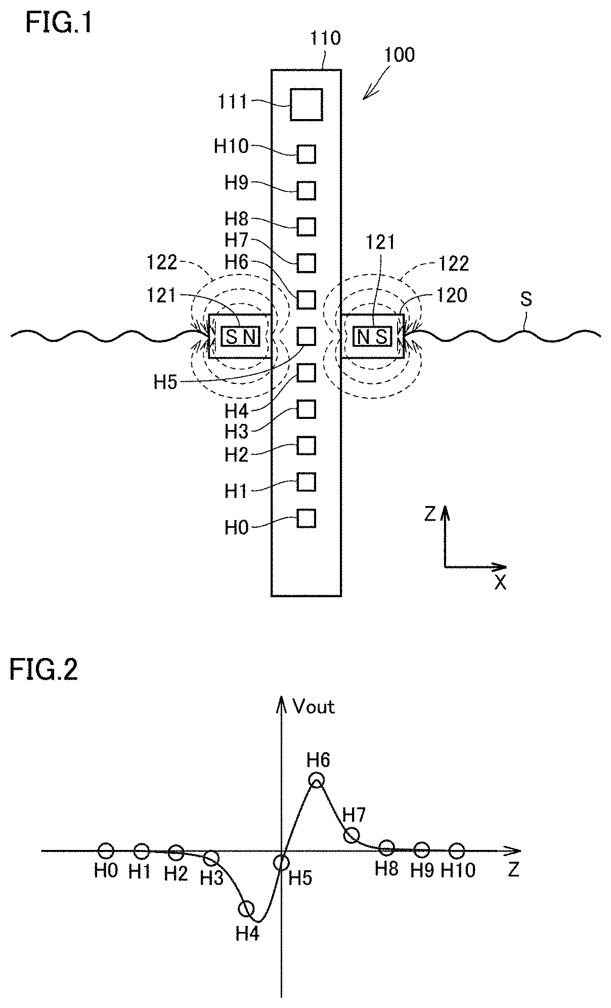
[0042]FIG. 1 is a sectional view showing a displacement detector device according to a preferred embodiment of the present invention. As shown in FIG. 1, a displacement detector device 100 according to a preferred embodiment of the present invention includes a substrate 110, multiple magnetic sensors H0 through H10, a magnet 121, and a controller 111. The Z-axis direction is a first direction,...


PUM

PropertyMeasurementUnit
temperatureaaaaaaaaaa
magnetic fieldaaaaaaaaaa

Abstract

In multiple magnetic sensors, for a correlation function between a magnetic field applied from a magnet and a value of the magnetic field detected by the magnetic sensor at a first temperature, the value detected by the magnetic sensor when the magnetic field applied from the magnet is 0 is set to be a first offset value. For a correlation function between a magnetic field applied from the magnet and a value of the magnetic field detected by the magnetic sensor at a second temperature, the value detected by the magnetic sensor when the magnetic field applied from the magnet is 0 is set to be a second offset value. The second temperature is higher than the first temperature. A values of applied magnetic fields detected by first and second magnetic sensors are opposite in polarity.

Description

CROSS REFERENCE TO RELATED APPLICATIONS[0001]This application claims the benefit of priority to Japanese Patent Application No. 2017-171064 filed on Sep. 6, 2017 and is a Continuation Application of PCT Application No. PCT / JP2018 / 030842 filed on Aug. 21, 2018. The entire contents of each application are hereby incorporated herein by reference.BACKGROUND OF THE INVENTION1. Field of the Invention[0002]The present invention relates to a displacement detector device, and more particularly, to a displacement detector device that detects a displacement of a magnet by using multiple magnetic sensors.2. Description of the Related Art[0003]Examples of the related art documents that disclose the configurations of displacement detector devices are Japanese Unexamined Patent Application Publication No. 2014-145714, Japanese Unexamined Patent Application Publication No. 2002-22403, and Japanese Unexamined Patent Application Publication No. 2002-277308.[0004]A liquid-surface-level detector device...

Claims


Application Information

Patent Timeline
Patent Type & Authority Patents(United States)
IPC IPC(8): G01R33/00G01R33/06
CPCG01R33/0005G01R33/06G01D3/036G01D5/145G01R33/0082G01R33/091G01B7/00G01F23/62
Inventor ITO, YOSHIHIRO
Owner MURATA MFG CO LTD
Why Eureka
Try Eureka