
System and method for implementing a zero-sequence current filter for a three-phase power system

a technology of zero-sequence current and power system, which is applied in the direction of electrical equipment, circuit arrangements, ac network circuit arrangements, etc., can solve problems such as unbalanced operations

Active Publication Date: 2021-07-06
SWITCHED SOURCE PB LLC
View PDF5 Cites 0 Cited by
  • Summary
  • Abstract
  • Description
  • Claims
  • Application Information

AI Technical Summary

Problems solved by technology

However, there are certain situations that can cause unbalanced operations.
The most severe of these would be a fault or short circuit.

Method used


Image

  • System and method for implementing a zero-sequence current filter for a three-phase power system
  • System and method for implementing a zero-sequence current filter for a three-phase power system
  • System and method for implementing a zero-sequence current filter for a three-phase power system

Examples


Embodiment Construction

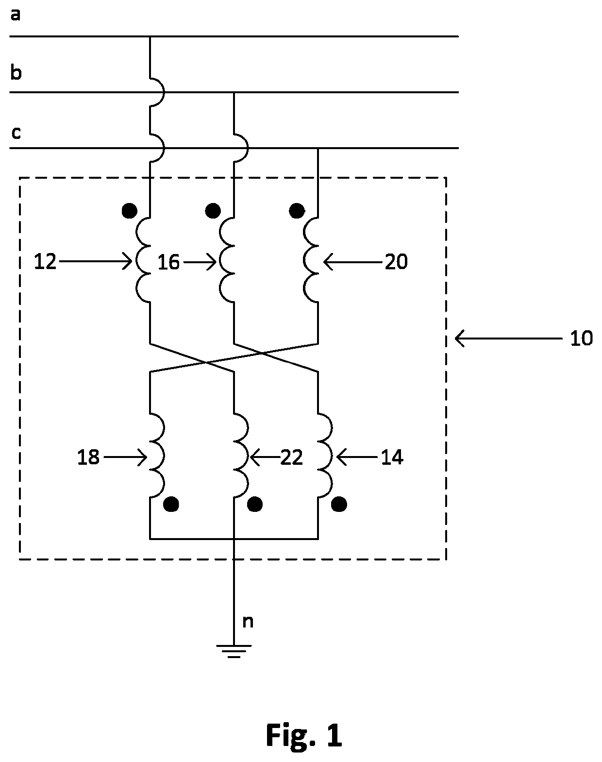
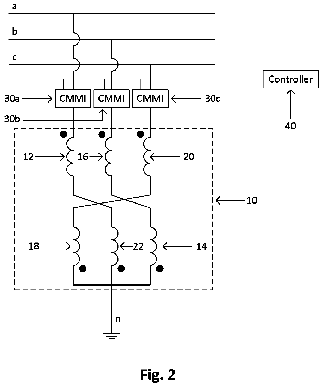
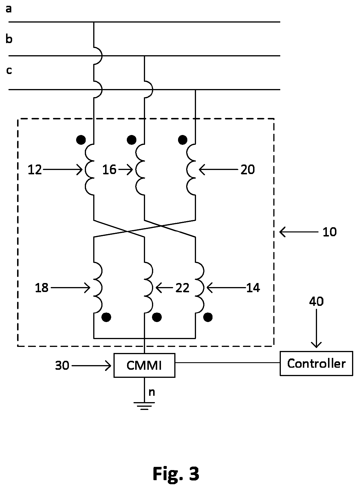
[0009]In one embodiment, a method for actively controlling zero-sequence current in a three-phase power distribution network having a phase A, a phase B, a phase C, and a neutral is disclosed, the method comprising the steps of: a) operatively coupling a first Cascade Multilevel Modular Inverter (CMMI) first terminal to phase A, and operatively coupling a first CMMI second terminal to a first primary winding dot terminal of a transformer; b) operatively coupling a second CMMI first terminal to phase B, and operatively coupling a second CMMI second terminal to a second primary winding dot terminal of the transformer; c) operatively coupling a third CMMI first terminal to phase C, and operatively coupling a third CMMI second terminal to a third primary winding dot terminal of the transformer; d) operatively coupling a third primary winding non-dot terminal of the transformer to a first secondary winding non-dot terminal of the transformer, wherein the first primary winding and the fir...


PUM

PropertyMeasurementUnit
magnetic fluxaaaaaaaaaa
voltageaaaaaaaaaa
equivalent impedanceaaaaaaaaaa

Abstract

In a three-phase, four-wire electrical distribution system, a zig-zag transformer and at least one Cascade Multilevel Modular Inverter (CMMI) is coupled between the distribution system and the neutral. A controller modulates the states of the H-bridges in the CMMI to build an AC waveform. The voltage is chosen by the controller in order to control an equivalent impedance that draws an appropriate neutral current through the zig-zag transformer. This neutral current is generally chosen to cancel the neutral current sensed in the line. In other embodiments, the chosen neutral current may be based on a remotely sensed imbalance, rather than on a local value, determined by the power utility as a critical load point in the system. The desired injection current is then translated by the controller into a desired zero-sequence reactive impedance, based on measurement of the local terminal voltage, allowing the controller to regulate the current without generating or consuming real power. In some embodiments, the zig-zag transformer is omitted.

Description

CROSS-REFERENCE TO RELATED APPLICATION[0001]This application is a continuation of U.S. application Ser. No. 16 / 864,094, entitled “SYSTEM AND METHOD FOR IMPLEMENTING A ZERO-SEQUENCE CURRENT FILTER FOR A THREE-PHASE POWER SYSTEM,” filed Apr. 30, 2020, which claims priority from U.S. Provisional Application 62 / 949,826 filed Dec. 18, 2019, the contents of which are hereby incorporated by reference in their entireties.[0002]The embodiments disclosed herein generally relate to three-phase power systems and, more specifically, to a system and method for implementing a zero-sequence current filter for a three-phase power system.BACKGROUND OF THE DISCLOSED EMBODIMENTS[0003]An electrical power system normally operates in a balanced three-phase sinusoidal steady-state mode. However, there are certain situations that can cause unbalanced operations. The most severe of these would be a fault or short circuit. Examples may include a tree in contact with a conductor, a lightning strike, or downed ...

Claims


Application Information

Patent Timeline
Patent Type & Authority Patents(United States)
IPC IPC(8): H02J3/18H01F30/12
CPCH02J3/1857H01F30/12H02J3/26Y02E40/50
Inventor BENAVIDES, NICHOLASROBBINS, BRETTCRADDOCK, THOMAS
Owner SWITCHED SOURCE PB LLC
Learn More