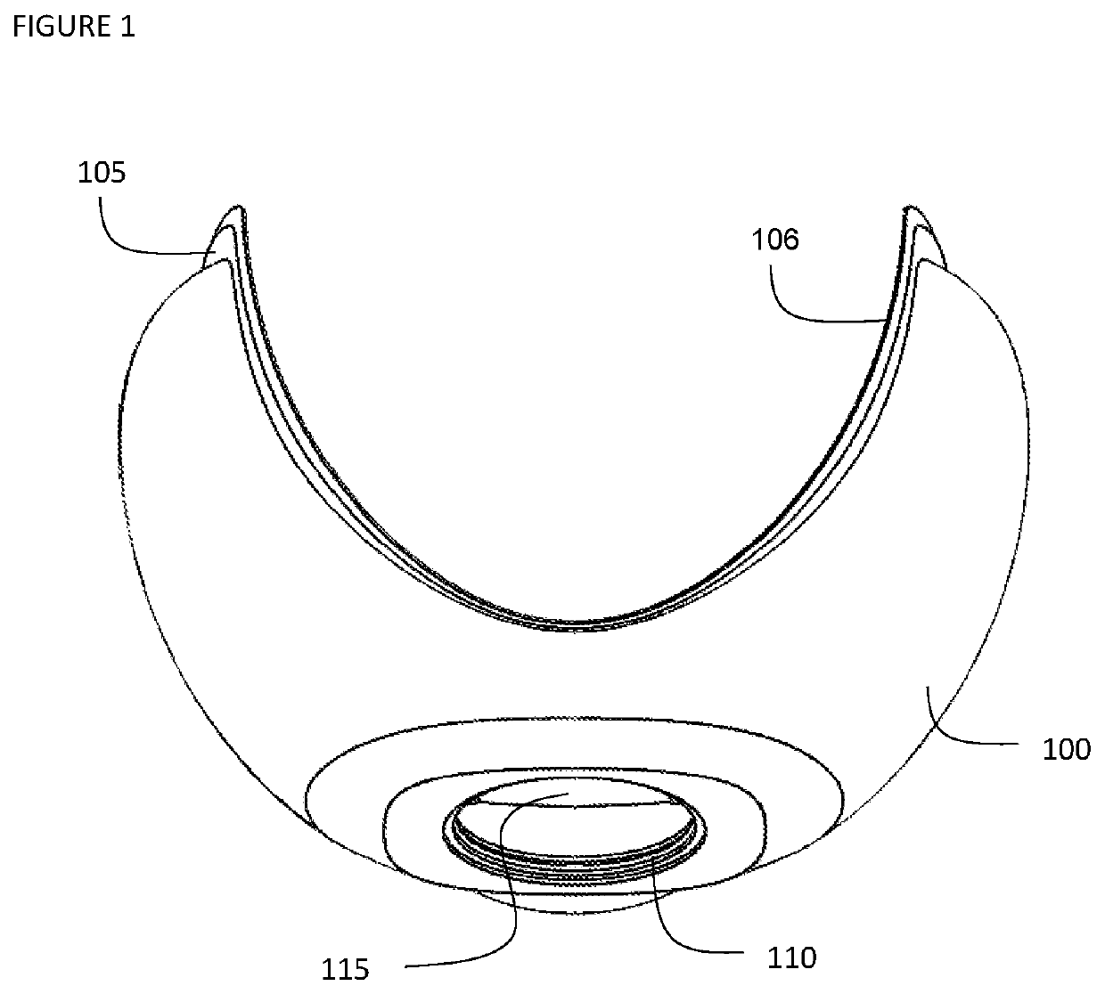
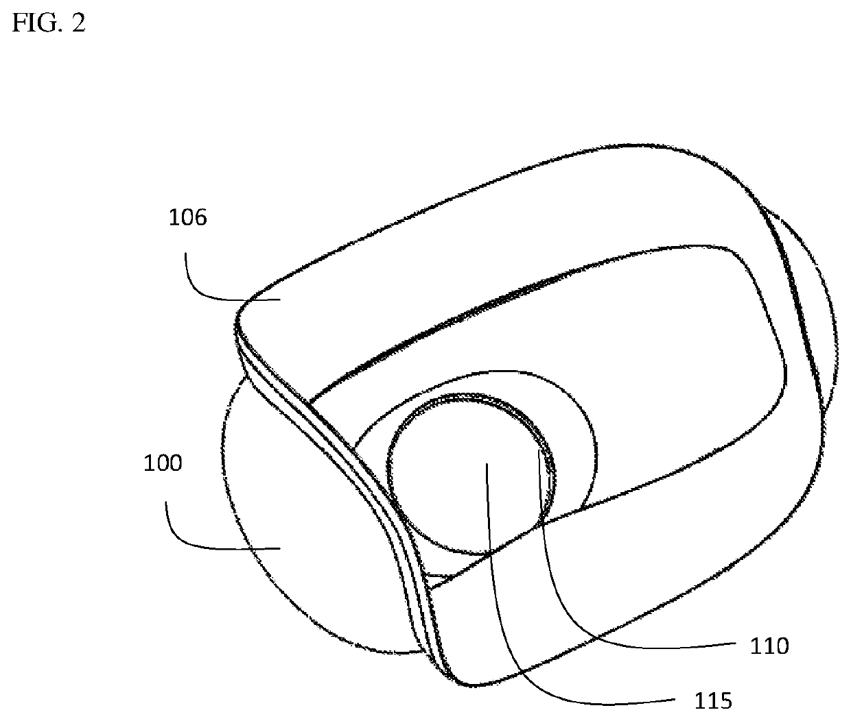
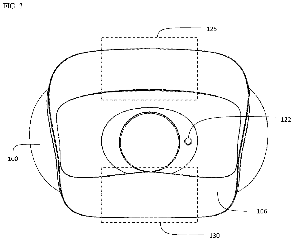
Device and method for opening an airway
a technology of airway and sealing flange, which is applied in the field of devices and methods for opening airways, can solve the problems of difficult to obtain a proper and comfortable fit between the apparatus and the patient, and the point of high pressure from the device's sealing flange element on the user's skin becoming too uncomfortable for continued use, and achieves the effect of increasing the patency of the airway of the individual
- Summary
- Abstract
- Description
- Claims
- Application Information
AI Technical Summary
Benefits of technology
Problems solved by technology
Method used
Image

Examples
Embodiment Construction
[0058]The present invention and the various features and advantageous details thereof are explained more fully with reference to the non-limiting embodiments that are illustrated in the accompanying drawings and detailed in the following description. It should be noted that the features illustrated in the drawings are not necessarily drawn to scale. Descriptions of well-known components and processing techniques are omitted so as to not unnecessarily obscure the present invention. The examples used herein are intended merely to facilitate an understanding of ways in which the invention may be practiced and to further enable those of skill in the art to practice the invention. Accordingly, the examples should not be construed as limiting the scope of the invention. In the drawings, like reference numerals designate corresponding parts throughout the several views.
[0059]In the present invention, a therapy device is designed for a negative pressure therapy device that maximizes comfort...
PUM
 Abstract
Description
Claims
Application Information
 - R&D Engineer
- R&D Manager
- IP Professional
- Industry Leading Data Capabilities
- Powerful AI technology
- Patent DNA Extraction
Browse by: Latest US Patents, China's latest patents, Technical Efficacy Thesaurus, Application Domain, Technology Topic.
© 2024 PatSnap. All rights reserved.Legal|Privacy policy|Modern Slavery Act Transparency Statement|Sitemap