Shroud lock

a technology of shroud and lock, which is applied in the field of shroud locks, can solve the problems of reducing the risk of needle-stick injury, and reducing the risk of failur

Active Publication Date: 2021-07-13
SANOFI AVENTIS DEUT GMBH
View PDF13 Cites 0 Cited by
  • Summary
  • Abstract
  • Description
  • Claims
  • Application Information

AI Technical Summary

Benefits of technology

[0012]a cap coupled to the housing and adapted to prevent distal translation of the needle shroud relative to the housing. At least a portion of the shroud beam is within the recess when the cap is in place. Furthermore, the shroud beam abuts the stop after the needle shroud is locked relative to the housing of the autoinjector.
[0013]The shroud lock provides a needle safety feature for an autoinjector by preventing translation of the needle shroud after the autoinjector is removed from the injection site. The radially outward bias of the shroud beam and the recess in the housing enable the shroud beam to be maintained in a relaxed state during storage to avoid or at least minimize the risk of failure due to creep of material.
[0014]In an exemplary embodiment, the needle shroud moves distally from a retracted position towards an extended position relative to the housing when the autoinjector is moved to a locked state. In this extended position, the needle shroud extends beyond a needle of the autoinjector and is locked in an axial position relative to the housing. Thus, a risk of needle-stick injury is reduced.

Problems solved by technology

Administering an injection is a process which presents a number of risks and challenges for users and healthcare professionals, both mental and physical.
There are numerous disadvantages associated with this approach.
For example, if the button / plunger is released prematurely, the injection will stop and may not deliver an intended dose.
Furthermore, the force required to push the button / plunger may be too high (e.g., if the user is elderly or a child).

Method used


Image

  • Shroud lock
  • Shroud lock
  • Shroud lock

Examples


Embodiment Construction

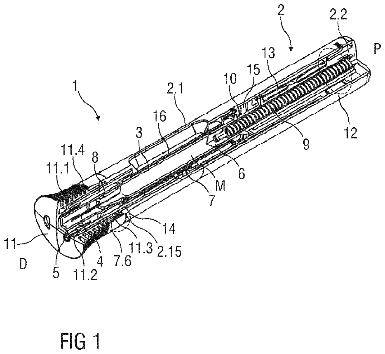
[0041]FIG. 1 is a schematic perspective partial section of an exemplary embodiment of an autoinjector 1 in a state after assembly.

[0042]The autoinjector 1 comprises a housing 2 including a sleeve shaped front part 2.1 and a rear part 2.2. The housing 2 is adapted to hold a syringe 3, e.g. a glass syringe. The syringe 3 may be a pre-filled syringe containing a liquid medicament M and have a needle 4 arranged on a distal end. In another exemplary embodiment, the syringe 3 may be a cartridge which includes the medicament M and engages a removable needle (e.g., by threads, snaps, friction, etc.). In the shown exemplary embodiment, the syringe 3 is held in the housing 2 and supported at its proximal end therein.

[0043]The autoinjector 1 further comprises a protective needle sheath 5 that is coupled to the needle 4. For example, the protective needle sheath 5 is removably coupled to the needle 4. The protective needle sheath 5 may be a rubber needle sheath or a rigid needle sheath which is...


PUM


Abstract

A shroud lock for locking a position of a needle shroud relative to a housing of an autoinjector, includes a shroud beam arranged on the needle shroud and biased radially outwards, a stop arranged within the housing, a recess arranged proximal of the stop, and a cap coupled to the housing and adapted to prevent distal translation of the needle shroud relative to the housing. At least a portion of the shroud beam is within the recess when the cap is in place and, the shroud beam abuts the stop after the needle shroud is locked relative to the housing of the autoinjector. The disclosure further relates to an autoinjector and to a method for assembling such an autoinjector.

Description

CROSS REFERENCE TO RELATED APPLICATIONS[0001]The present application is the national stage entry of International Patent Application No. PCT / EP2016 / 062458, filed on Jun. 2, 2016, and claims priority to Application No. EP 15170594.4, filed on Jun. 3, 2015, the disclosures of which are expressly incorporated herein in entirety by reference thereto.TECHNICAL FIELD[0002]The disclosure relates to a shroud lock and to an autoinjector. The disclosure further relates to a method for assembling an autoinjector.BACKGROUND[0003]Administering an injection is a process which presents a number of risks and challenges for users and healthcare professionals, both mental and physical. Injection devices typically fall into two categories—manual devices and autoinjectors. In a conventional manual device, manual force is required to drive a medicament through a needle. This is typically done by some form of button / plunger that has to be continuously pressed during the injection. There are numerous disa...

Claims


Application Information

Patent Timeline
Patent Type & Authority Patents(United States)
IPC IPC(8): A61M5/32A61M5/20A61M5/315
CPCA61M5/3245A61M5/2033A61M5/3202A61M5/3243A61M5/3157A61M2005/3247A61M2005/3267A61M2205/581A61M5/326A61M5/20
Inventor MOSEBACH, CARSTENKEMP, THOMAS MARK
Owner SANOFI AVENTIS DEUT GMBH
Why Eureka
Try Eureka