Puncture tool guiding device

a guiding device and tool technology, applied in the field of guiding devices of tools for punching, can solve the problems of angle shift and deviation during tapping or screw insertion, serious disability, and variation in insertion accuracy, and achieve the effect of accurate guiding and accurate inserting position

Active Publication Date: 2021-07-20
KK KKYSS
View PDF9 Cites 0 Cited by
  • Summary
  • Abstract
  • Description
  • Claims
  • Application Information

AI Technical Summary

Benefits of technology

[0018]According to the present invention, when a puncture tool is passed through a guide hole formed in a sleeve, the tool can be accurately guided at an insertion angle. In particular, a slit is formed in the sleeve, and hence, an arbitrary angle can be seen by X-ray fluoroscopy. For example, an angle of the sleeve in which slits are formed is set to 40 degrees in advance and the angle is accurately 40 degrees. In this case, when seen by the X-ray fluoroscopy, each slit is aligned and can be clearly seen through the sleeve. When the angle shifts from 40 degrees, the width of each slit looks small, or any slits cannot be seen at all. That is, the angle can be seen by the X-ray fluoroscopy.
[0019]Furthermore, in the sleeve, when through holes formed in opposite tubular walls are linearly superimposed, the holes can be seen through the sleeve by fluoroscopy in an X-axis direction. Consequently, rotation of the sleeve can be seen, and an accurate inserting position can be grasped also in a Y-axis direction.

Problems solved by technology

In particular, there is concern that, when the probe or the like that is the puncture tool is inserted into a wrong position to form the pilot hole in the cervical spine, serious disability is caused in the above organ.
However, there is a problem that such an operation of the probe without any guide is greatly influenced by an amount of experience and a skill of an operator and that variation in insertion accuracy is generated.
Furthermore, even after the probe is accurately inserted, there is still concern that an angle shifts and deviates during tapping or screw insertion.

Method used


Image

  • Puncture tool guiding device
  • Puncture tool guiding device
  • Puncture tool guiding device

Examples


Embodiment Construction

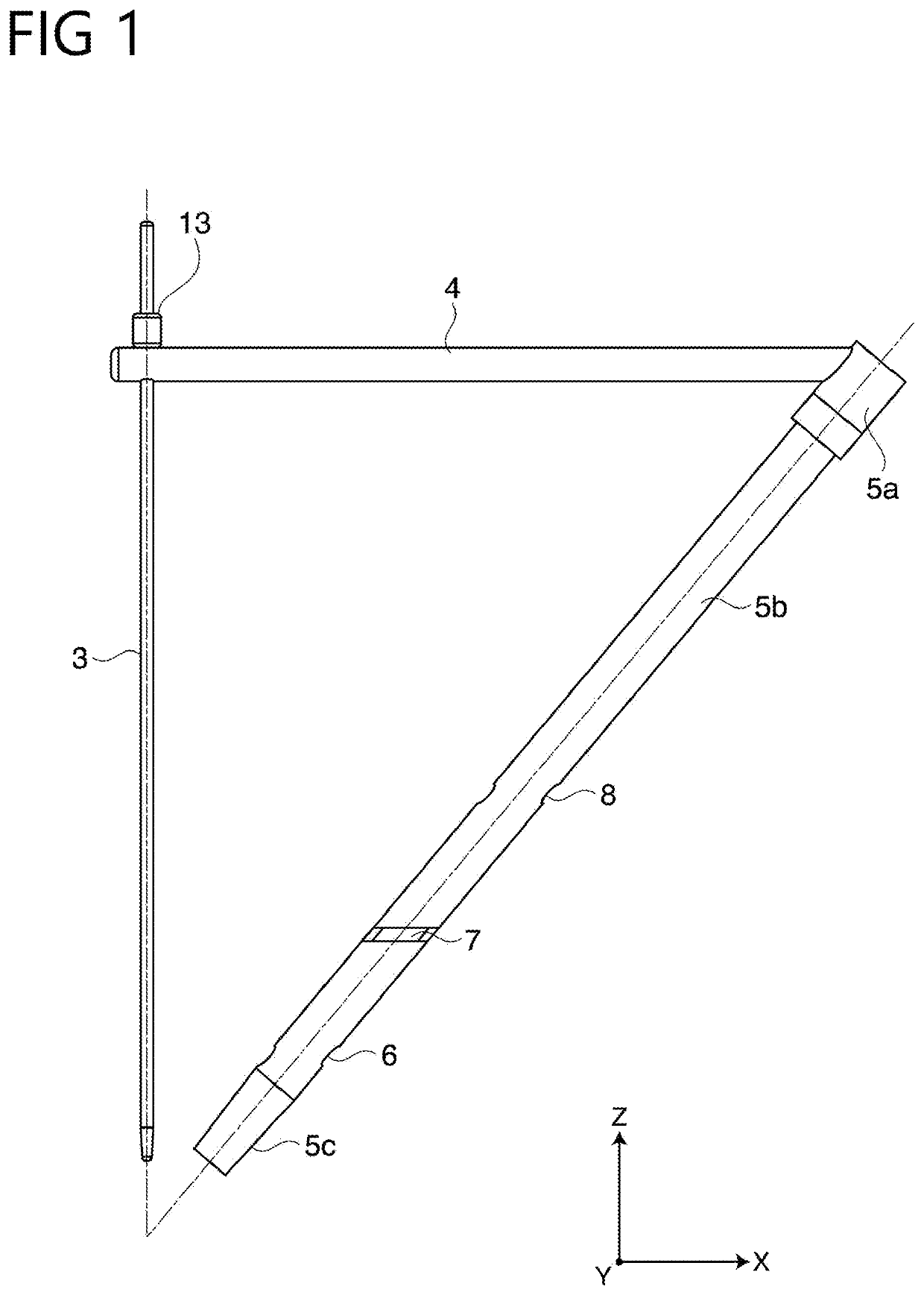
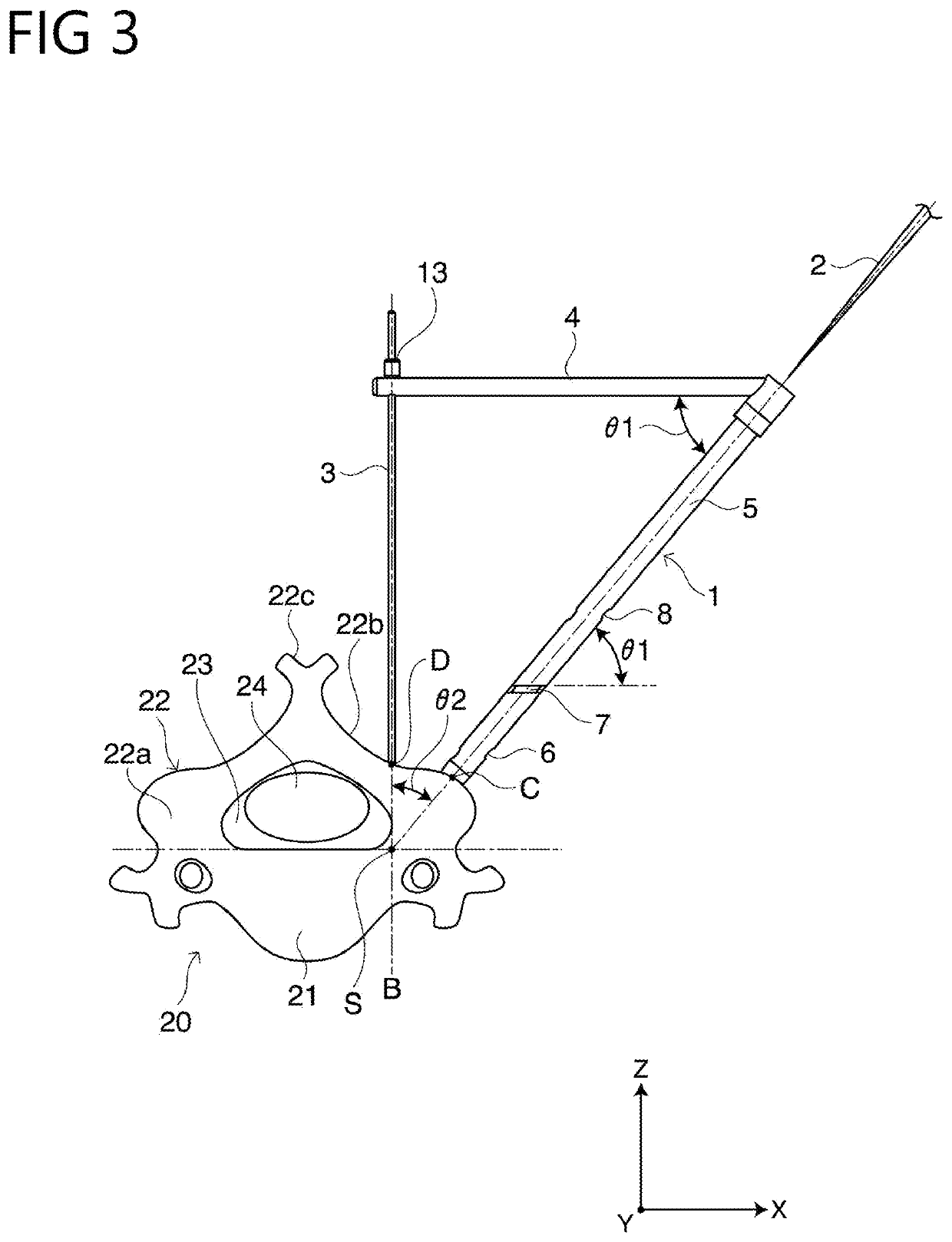
[0026]Hereinafter, an embodiment of the present invention will be described with reference to the drawings. A puncture tool guiding device 1 in the present embodiment guides a puncture tool 2 to form a pilot hole through which a pedicle screw is buried in a pedicle.

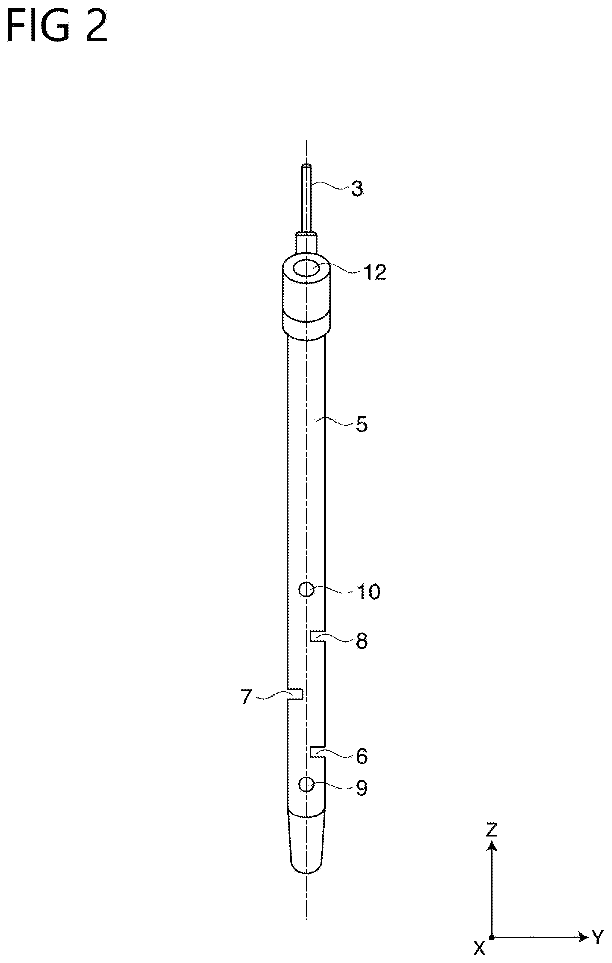
[0027]The puncture tool guiding device 1 includes a reference pin 3 that is disposed forward from a rear side of a spine toward a target point S on a pedicle base and serves as a reference, a linear rod member 4 having one end portion located on a proximal side of the reference pin 3 and another end portion laterally extending, and a tubular sleeve 5 installed in the other end portion of the rod member 4 at a first predetermined angle θ1 to the rod member 4, and having a distal end that is open toward the target point S (that may be hereinafter referred to simply as “point S”) and through which the puncture tool 2 is passed and guided.

[0028]Furthermore, a plurality of slits 6, 7 and 8 are formed in a side surface of the s...


PUM


Abstract

A device for guiding a puncture tool to form a pilot hole through which a pedicle screw is buried in a pedicle, the device including a linear reference pin disposed forward from a rear side of a spine toward a target point of a pedicle base; a tubular sleeve having a sleeve central axis disposed at a predetermined insertion angle to the reference pin, and having a distal end open toward the target point and through which the puncture tool is passed and guided; and a rod member that couples a proximal side of the reference pin to the sleeve and maintains the sleeve central axis at the predetermined insertion angle to the reference pin. Plural slits are formed with a cutting direction orthogonal to the reference pin. A shape of a slit portion is recognized by an X-ray fluoroscopic image, and the puncture tool can be easily guided.

Description

TECHNICAL FIELD[0001]The present invention relates to a puncture tool guiding device to accurately guide an inserting position and direction of a puncture tool, when a pilot hole, through which a pedicle screw for use in spinal fusion that is a surgical operation of a spine is buried, is formed in a vertebra with the puncture tool.BACKGROUND ART[0002]In fusion of a cervical spine or the like, a technique of burying a pedicle screw in a spine is frequently adopted. This pedicle screw is buried by inserting a puncture tool such as a probe to form a pilot hole in advance, and screwing the pedicle screw into the pilot hole.[0003]Now, important organs such as a spinal cord, a nerve root, a blood vessel and an internal organ are located densely around the spine. In particular, there is concern that, when the probe or the like that is the puncture tool is inserted into a wrong position to form the pilot hole in the cervical spine, serious disability is caused in the above organ. Therefore,...

Claims


Application Information

Patent Timeline
Patent Type & Authority Patents(United States)
IPC IPC(8): A61B17/17A61B17/16A61B17/70
CPCA61B17/1757A61B17/1671A61B17/1703A61B17/7002A61B17/17A61B17/70A61B17/1728A61B17/7074A61B17/3472
Inventor SUDA, KOTA
Owner KK KKYSS
Why Eureka
Try Eureka