External control for hot water recirculation pump

a technology for external control and hot water recirculation, which is applied in the direction of domestic hot water supply systems, lighting and heating apparatus, heating types, etc. it can solve the problems of all utilized alternating house current to power relatively inefficient pumps, and achieve the effect of minimal loss of heat energy

Active Publication Date: 2021-07-27
TACO
View PDF20 Cites 0 Cited by
  • Summary
  • Abstract
  • Description
  • Claims
  • Application Information

AI Technical Summary

Benefits of technology

[0004]The present invention reflects the novel recognition that many households have previously installed a simple manual or pulse mode pump, and did not want to go through the expense and time of buying a new smart pump. It has now been discovered that rather than purchasing an entirely new pump system, the external control unit of the present invention can be connected between the power source and the pump to act as a ‘smart switch, to convert a ‘dumb’ pump into a smart pump. This invention is especially useful for use with the relatively small pump-motor combinations used to maintain a minimal flow of hot water, through a hot water system and returned to the hot water source, in order to provide substantially instantaneous hot water whenever a tap is turned on anywhere in the system. This system allows for a minimal loss of heat energy, especially during the winter in the northern states, in that water flow, and therefore the energy for heating water, is limited only by the temperature at which the user wants the hot water to be maintained.

Problems solved by technology

The prior devices all utilized alternating house current to power relatively inefficient pumps, located either at or near the hot water tank; these were installed especially during new house construction, or located at the farthest tap site and pumping between the hot and cold water lines at those locations, for aftermarket installation in older buildings.

Method used


Image

  • External control for hot water recirculation pump
  • External control for hot water recirculation pump
  • External control for hot water recirculation pump

Examples


Embodiment Construction

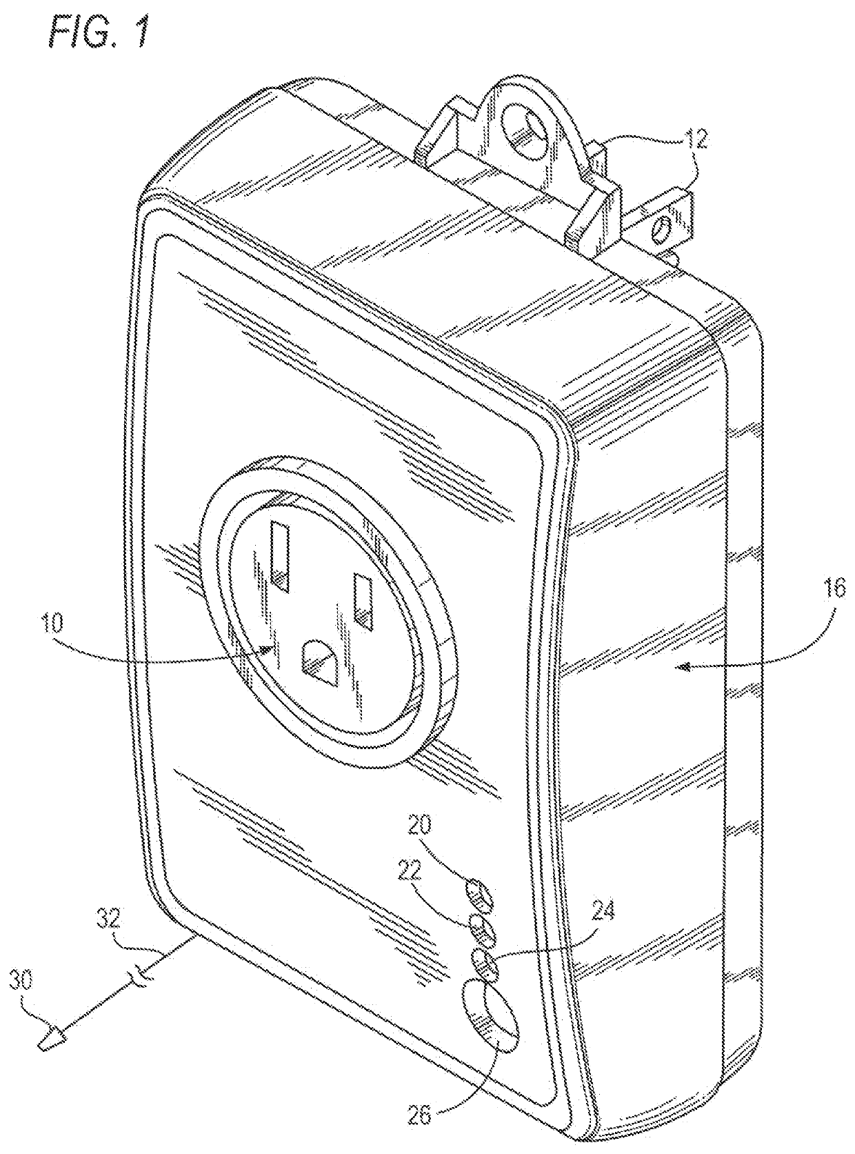
[0021]Referring to FIG. 1, there is shown the external programmed control unit of the present invention. As shown this control unit includes an outer case, generally indicated by the numeral 16, which, on its front face, has socket openings 10 to receive a conventional three-prong electric plug, three LED indicators 20, 22, 24, and a toggle switch 26, all on its front face. Protruding from the rear face is a three-prong standard plug 12 intended to be inserted into a three-prong wall outlet standard in the United States. Alternatively, the prongs on the back and the receptacle on the front face can be made in accordance with the standards in any other country. The case can be, e.g., 3 in.×5 in.×1.5 in. in size.

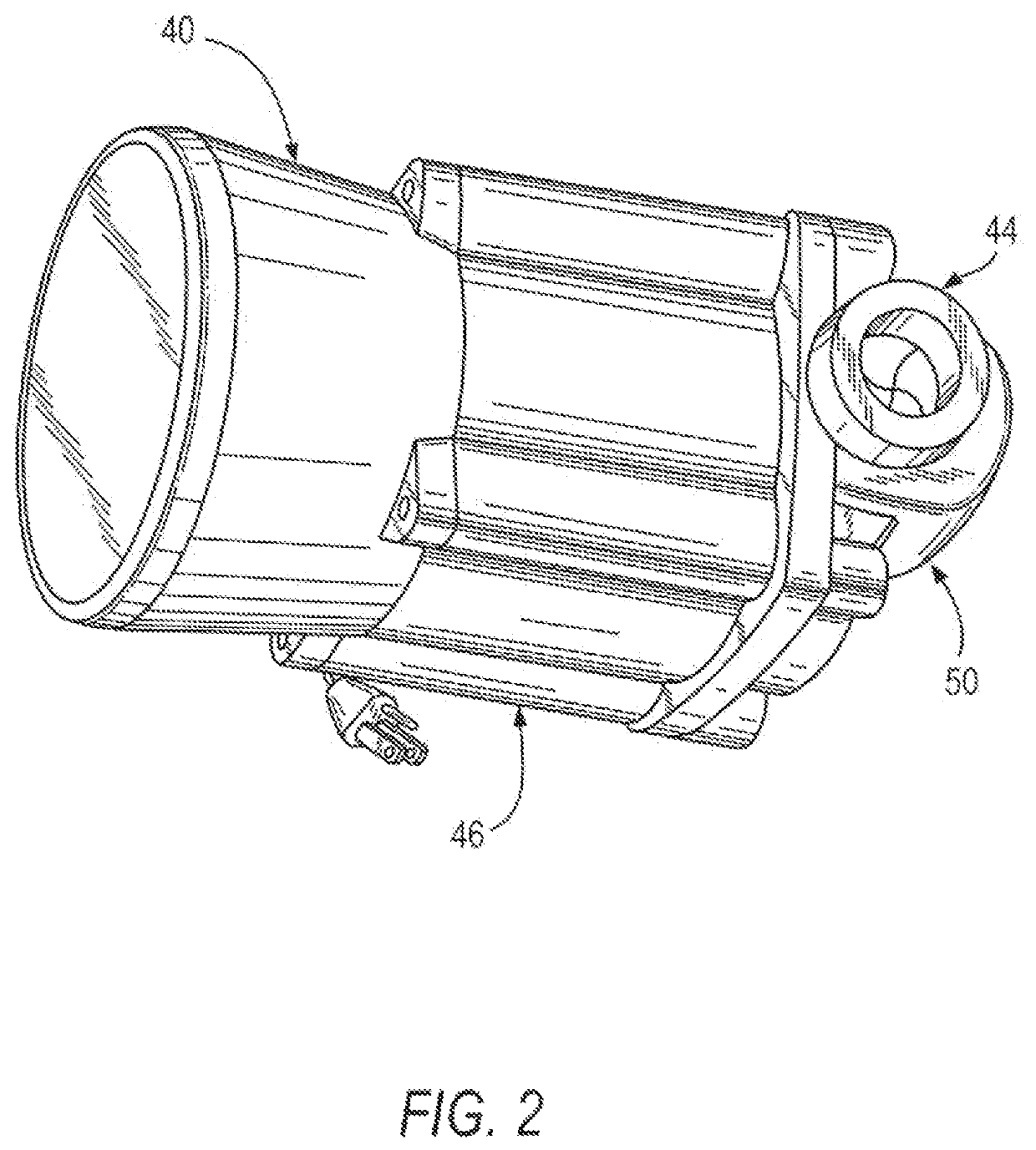
[0022]FIG. 2 is an example of a commonly used rotary impeller pump operated by a motor powered by household electric current.

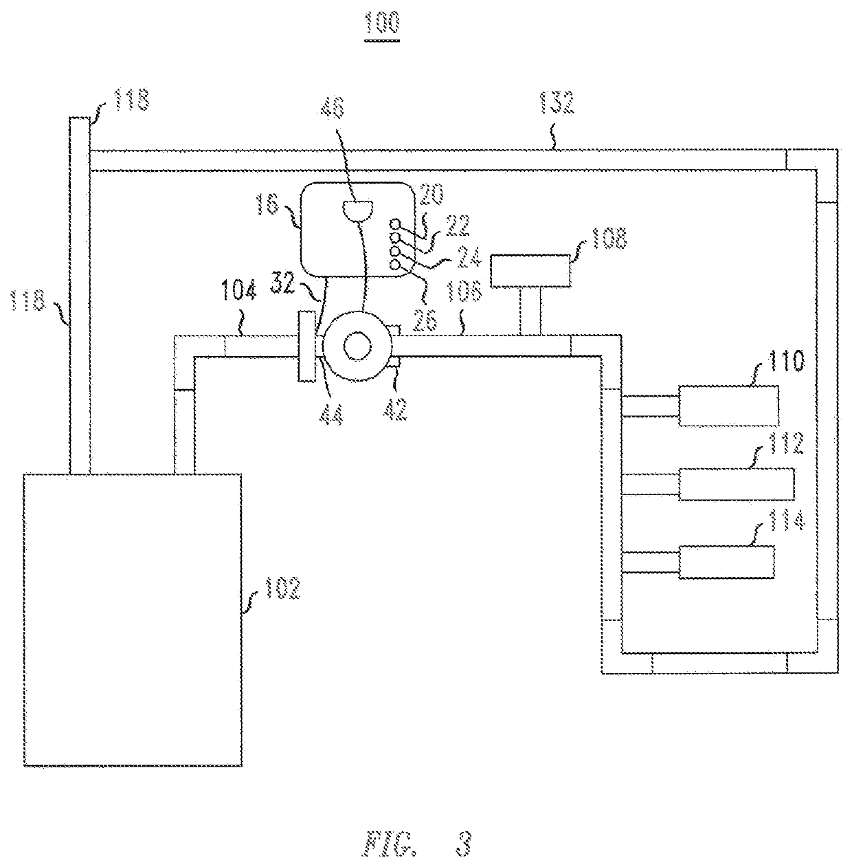
[0023]Referring to FIG. 3, the system of this invention is shown in the context of a closed water system of a household. The system has a hot water tank...


PUM


Abstract

An external control unit to be connected between a power source and an electrically driven pump to act as a smart switch to convert a “dumb” pump into a smart pump. The control system of this invention comprises a microcontroller-operated switch, located between the power source and the pump, or other fluid flow control device to be operated by electricity, and which can be programmed to record usage data of, e.g., hot water, by the household; it sets up the operating times in accordance with such usage. A temperature sensor is connected to the microcontroller to sense a temperature change, in a hot water system is turned on, by measuring an increase in temperature to indicate flow through the hot water pipe, and to record such data. This will determine, in the context of a hot water system, when the pump should be activated to bring up hot water.

Description

FIELD OF THE INVENTION[0001]The present invention relates to a small, external unit for controlling a small water pump that will plug directly into a standard, properly grounded, 120 volt electrical wall outlet. The small unit contains an electronic control board that will operate a pump, i.e., turn a pump “on” and “off,” that is, e.g., plugged into it, that is receiving the electrical power it needs to operate through the small, external control unit. It can provide at least two (2) modes of operation for the pump, i.e., a Smart Mode and a Pulse Mode.DESCRIPTION OF THE RELATED ART[0002]In many of the dry, or drought-plagued parts of North America, and possibly elsewhere, hot water is often continually circulated within the closed water system of a house or business, in order to have hot water substantially immediately available when a faucet is turned on; this avoids, or at least reduces, the wasting of flowing water while waiting for the hot water to reach a tap in a bathroom or k...

Claims


Application Information

Patent Timeline
Patent Type & Authority Patents(United States)
IPC IPC(8): F24D19/10E03B7/04F24D17/00
CPCF24D19/1051E03B7/04F24D17/0078F24D2220/0207
Inventor KELLICKER, ROBERTPERRONE, JR., CARL A.
Owner TACO
Why Eureka
Try Eureka