Purge procedure for a decoupled brake system and brake system implementing this procedure

a brake system and purging device technology, applied in the direction of brake systems, vehicle sub-unit features, brake components, etc., can solve the problems of complex manufacturing of the different connections between the brake fluid reservoir and the wheel brake, the operation cannot be carried out in a factory or specially equipped workshop, and the decoupling brake system or circuit is becoming increasingly complex. to achieve the effect of effective and complete purging of the brake circui

Active Publication Date: 2021-08-24
ROBERT BOSCH GMBH
View PDF10 Cites 0 Cited by
  • Summary
  • Abstract
  • Description
  • Claims
  • Application Information

AI Technical Summary

Benefits of technology

[0011]An object of the present invention is an apparatus / arrangement for effectively and completely purging the brake circuit with a brake system apparatus / arrangement.
[0012]To that end, the object of the invention is a purging procedure of a decoupled brake system of the type described above, characterized in that we select a site likely to contain a gas pocket to be purged from the brake circuit, we define a channel segment having a first extremity and a second extremity, each equipped with a solenoid valve encompassing the site and a pressure / vacuum source with a solenoid valve intermediate between the site and the pressure / vacuum source, delimiting an outgoing subsegment; the second extremity beyond the corresponding solenoid valve being allowed to communicate with the outside atmosphere, the solenoid valves at the extremities are closed and the intermediate solenoid valve opened, thus creating a vacuum with the source in the isolated segment, this vacuum being maintained throughout a period dependent on the parameters of the isolated segment, then, the intermediate solenoid valve is closed to trap, beyond this intermediate solenoid valve, in the outgoing subsegment, the gas pocket or a gas bubble that has migrated beyond this intermediate solenoid valve; the solenoid valve at the second extremity of the channel segment is opened to open communication of the subsegment with the outlet, and pressure is applied by the pressure / vacuum source in the subsegment between the intermediate solenoid valve and the outlet to evacuate the gas bubble through the outlet. This purge procedure has the advantage of using an apparatus / arrangement existing in the brake system without requiring specific specialized equipment outside the motor and the brake circuits connected to the wheel brakes. It allows such a purge operation to be carried out independently of any external specialized equipment, the brake system control unit simply providing, on one hand, the closing and opening of the solenoid valves in sync with the depressurization and pressurization.
[0015]According to another advantageous characteristic, the source of the vacuum / pressure is the brake circuit pump whose plunger is controlled to create a vacuum, the plunger being maintained in the vacuum position throughout the vacuum stabilization period and at the end of the vacuum phase, one of the solenoid valves of the segment is opened to connect the segment to the outside atmosphere and the pump is directed so that its plunger applies pressure to the segment. The procedure using the brake circuit pump to create the vacuum is especially advantageous because it requires no intervention to the brake system other than in the brake circuit and this through the automatic control of the valves involved to ensure isolation of the segment, followed by the opening of one of these extremities to the outside atmosphere, and finally control of the pump plunger to create a vacuum movement and then a pressure movement. The specific nature of the pump equipping the brake circuit allows the vacuum phase and the pressure phase to be clearly separated through the simple translation of the plunger by the pump motor.
[0018]According to another advantageous characteristic, the decoupled brake system comprises: a brake fluid reservoir, a master cylinder connected to the brake pedal by a thrust rod, a pedal travel sensor detecting the travel of the thrust rod, a brake circuit connecting the master cylinder to the wheel brakes, and a management unit to manage operation of the brake system based on the request for braking resulting from actuation of the brake pedal. This brake system according to the invention is characterized in that the management unit managing operation of the brake system contains a program to control implementation of the purge procedure as described above. This brake system has the advantage of not requiring any component other than those already existing in the brake system, the only addition being a control program for the solenoid valves and the pump and the master cylinder to activate these different components according to the steps of the program to be carried out.

Problems solved by technology

However, such decoupled brake systems or circuits are becoming increasingly complex due to the growing number of components such as solenoid valves, hydraulic pistons, and cavities.
Additionally, because these brake systems are increasingly integrated and compact, in general, this results in an electro-hydraulic unit connected to different sensors such as the brake pedal actuator sensor, the pressure sensors throughout the circuit, information about vehicle and wheel movement that generates wheel brake control signals based on these parameters and the braking programs from the brake system's central management unit.
The electro-hydraulic unit or distribution unit that provides these different connections between the brake fluid reservoir and the wheel brakes is extremely complex in terms of its manufacture given that the channels are made by drilling into the unit.
But such an operation can only be carried out in a factory or specially equipped workshop.
Whenever the process must be carried out on the brake circuit either on site or in a workshop, it is difficult to ensure that the brake channels will be perfectly filled with brake fluid.
But such air pockets result in operational defects or poor braking characteristics.
In short, these non-specialized arrangements do not provide a way to ensure the complete purging of the brake circuit.

Method used


Image

  • Purge procedure for a decoupled brake system and brake system implementing this procedure
  • Purge procedure for a decoupled brake system and brake system implementing this procedure
  • Purge procedure for a decoupled brake system and brake system implementing this procedure

Examples


Embodiment Construction

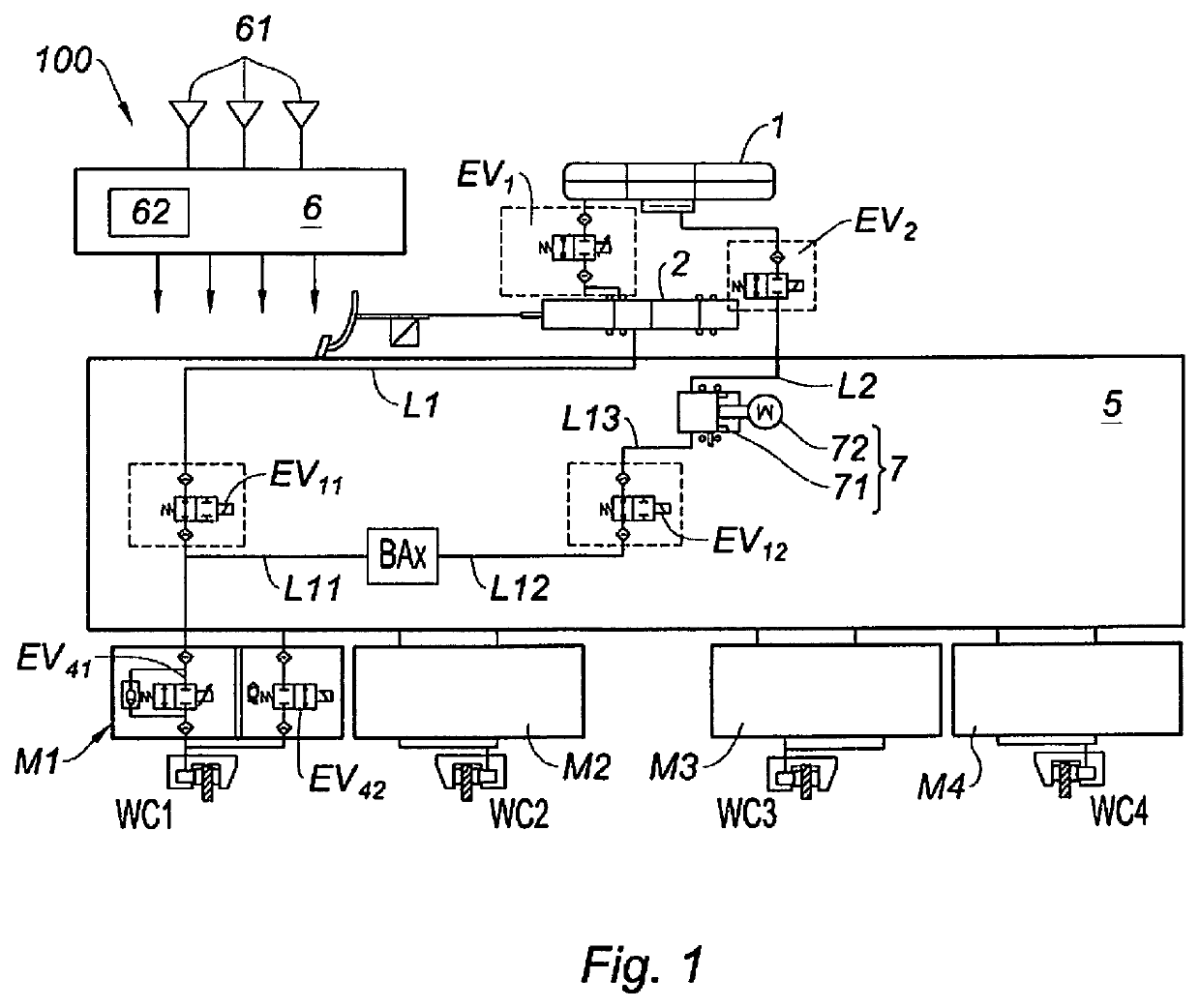
[0025]According to FIG. 1, the invention relates to a decoupled brake system 100 to which is applied the purge procedure according to the invention. Brake system 100 consists of brake fluid reservoir 1 connected to wheel brakes WC1-WC4 by tandem master cylinder 2 and brake circuit 5, which distributes the brake fluid among wheel brakes WC1-WC4 by brake fluid pressurization pump 7 and a set of solenoid valves.

[0026]Wheel brakes WC1-WC4 are each represented by a brake caliper on the brake disc associated with the wheel, not shown, and having a hydraulic actuator. Wheel brakes WC1-WC4 are connected to circuit 5 by inlet modules M1-M4, enabling each wheel brake WC1-WC4 to be cut with respect to circuit 5.

[0027]Tandem master cylinder 2 is decoupled from brake pedal 3; it acts on wheel brakes WC1-WC4 only in the event of a failure of brake circuit 5, to then supply brake fluid at the pressure generated by the force alone exerted on brake pedal 3.

[0028]During normal operation, tandem maste...


PUM


Abstract

A method (purge procedure) for purging a decoupled brake system including: a brake fluid reservoir, a master cylinder, a brake circuit connected to the wheel brakes, a pump equipped with a plunger. A segment of the brake circuit to be purged is isolated by closing the solenoid valves at the extremities of the segment, a vacuum is created with the plunger, and an extremity of this segment is placed in communication with the exterior to evacuate the trapped air bubble.

Description

RELATED APPLICATION INFORMATION[0001]The present application claims priority to and the benefit of French patent application no. 1900031, which was filed in France on Jan. 3, 2019, the disclosure of which is incorporated herein by reference.FIELD OF THE INVENTION[0002]The present invention concerns a procedure and a purge device for a decoupled brake system still called an electric brake system. The decoupled brake system comprises: a brake fluid reservoir, a master cylinder connected to the brake pedal, a brake circuit connecting the master cylinder to the wheel brakes, and a management unit to manage operation of the brake system by a program and based on the braking request resulting from actuation of the brake pedal.BACKGROUND INFORMATION[0003]Decoupled brake systems are seeing greater and greater development; they do not have a vacuum brake booster and control the phases of braking through actuation of the brake pedal, thereby pressurizing the brake circuit by a controlled actu...

Claims


Application Information

Patent Timeline
Patent Type & Authority Patents(United States)
IPC IPC(8): B60T17/22B60T11/30B60T8/32B60T13/16
CPCB60T17/222B60T11/30B60T8/326B60T13/161B60T2270/82B60T17/18B60T17/00B60T17/004B60T11/323B60T8/174B60T13/72B60T8/425B60T7/042B60T8/404B60T2220/04B60Y2400/81
Inventor ANDERSON, CHRIS
Owner ROBERT BOSCH GMBH
Why Eureka
Try Eureka