Medical air treatment device

a medical air treatment and air technology, applied in the direction of lighting and heating apparatus, heating types, separation processes, etc., can solve the problems of significant airborne pathogens, high human and financial costs for the health care system, and pathogens that can generate significant risks for both health care professionals and other patients

Active Publication Date: 2020-07-07
AEROBIOTIX
View PDF49 Cites 8 Cited by
  • Summary
  • Abstract
  • Description
  • Claims
  • Application Information

AI Technical Summary

Benefits of technology

[0005]What is therefore needed is a device which can create a localized negative pressure zone around a patient within a normal pressure room. This will have the benefit of allowing the use of regular patient rooms as procedure rooms without requiring patient transportation. It will also offer a degree of exposure reduction to personnel within the room, as pathogens will directly enter the device and not the ambient room air. In order for such a device to work, it will need to be capable of creating a vacuum near the patient, have a filtration system to trap air contaminants and an irradiation system to inactivate bacteria.

Problems solved by technology

These agents contribute greatly to hospital acquired infections which drive great human and financial costs to the health care system.
Pulmonary and airway procedures such as bronchoscopy, laryngoscopy and airway intubation can generate significant airborne pathogens, particularly if the patient is already infected with transmissible agents such as tuberculosis or influenza.
These pathogens can generate significant risk to both health care professionals and other patients.
Furthermore, the emergence of drug resistant organisms make treatment of hospital acquired infections more difficult.
Negative pressure rooms, however, present significant problems.
First, these rooms have significant engineering requirements, and a typical hospital has a limited supply of such rooms.
The volume of procedures can outnumber the negative pressure facilities available.
Often it is impractical to transfer patients into negative pressure rooms in order to perform a procedure.
Patients may be critically ill, and transfer is risky.
Finally, negative pressure rooms do not offer protection for the medical personnel inside of the room.
Due to these limitations, hospitals are performing these procedures in normal-pressure patient rooms, intensive care units, and operating rooms.

Method used


Image

  • Medical air treatment device
  • Medical air treatment device
  • Medical air treatment device

Examples


Embodiment Construction

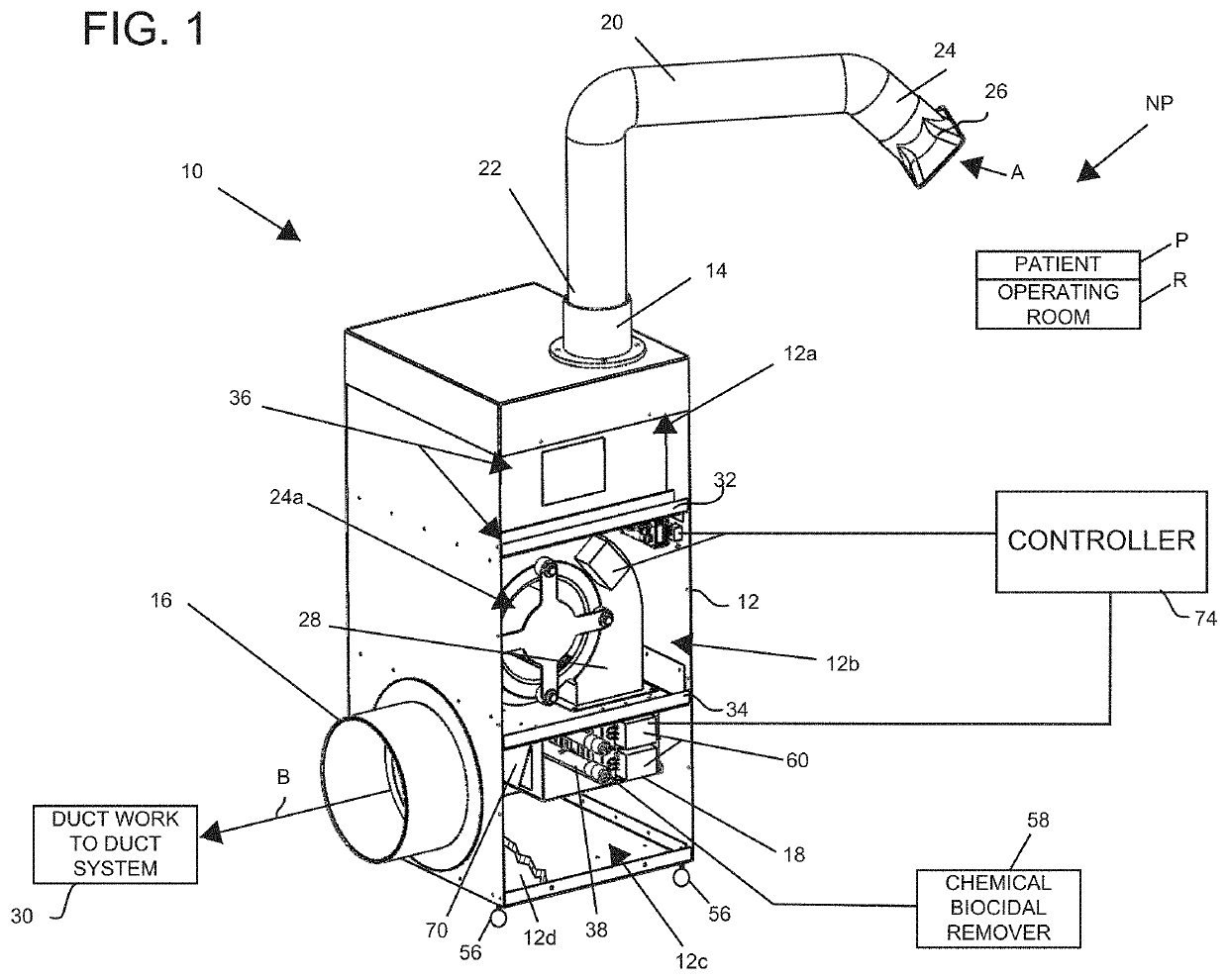
[0062]Referring now to FIG. 1, an air treatment system 10 is shown. The air treatment system 10 is adapted for use during a surgical procedure in a room, such as an operating room R, where it is desired to treat or purify the air around a patient P.

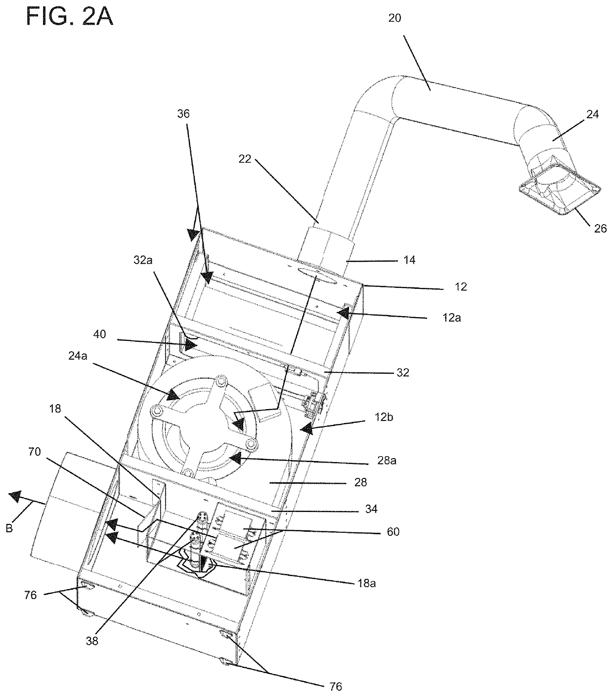
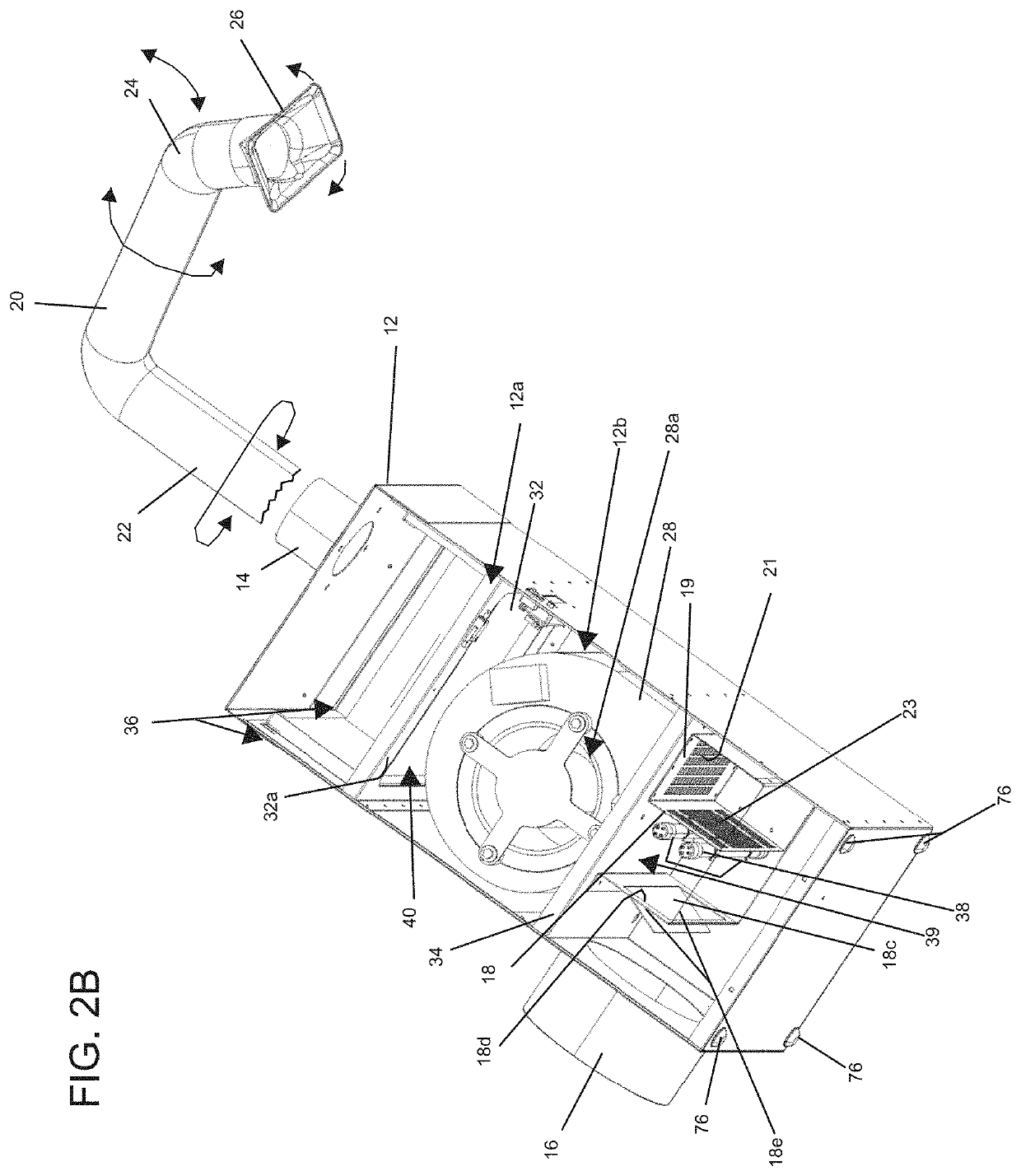
[0063]The air treatment system 10 comprises a housing 12 having an inlet 14 and an outlet 16. The housing 12 has an air treatment device 18 situated and mounted therein. The air treatment device 18 is adapted to filter, treat, sanitize and / or irradiate the air entering the inlet 14 and passing through the air treatment system 10 before exiting the outlet 16.

[0064]The air treatment system 10 comprises an air hose or duct 20 adapted to be mounted in communication with the inlet 14. In this regard, the air hose or duct 20 comprises an end 22 that is mounted to and in communication with the inlet 14 as illustrated in FIG. 1. The air hose or duct 20 has an inlet end 24 having a nozzle 26 detachably secured thereto. In the embodiments being des...


PUM

PropertyMeasurementUnit
pressureaaaaaaaaaa
pressureaaaaaaaaaa
air velocityaaaaaaaaaa

Abstract

An air treatment device having a flexible air hose, duct or gooseneck member. The air hose, duct or gooseneck member permits an inlet end thereof to be positioned in proximity to a patient so that a negative pressure can be created around the patient so that air can sucked or vacuumed into the system whereupon it is treated as the air flows through the system.

Description

CROSS-REFERENCE TO RELATED APPLICATION[0001]The present application claims priority to provisional U.S. Application Ser. No. 62 / 422,810 filed Nov. 16, 2016, to which Applicant claims the benefit of the earlier filing date. This provisional application is incorporated herein by reference and made a part hereof.BACKGROUND OF THE INVENTION1. Field of the Invention[0002]This invention relates to an air treatment device and, more particularly, an air treatment device having a flexible duct, hose or gooseneck adapted to permit a nozzle end to be situated in proximity to a patient.2. Description of the Related Art[0003]Health care settings are common grounds for the proliferation of airborne bacteria, viruses and fungi. These agents contribute greatly to hospital acquired infections which drive great human and financial costs to the health care system. A specific concern is the introduction of airborne pathogens arising from certain medical procedures. Pulmonary and airway procedures such ...

Claims


Application Information

Patent Timeline
Patent Type & Authority Patents(United States)
IPC IPC(8): B01D15/00A61L9/015A61G13/10B01D46/00A61M1/00F24F3/16A61L9/20B01D15/04F24F8/22F24F8/24
CPCF24F3/16A61L9/20B01D46/0028A61L9/015A61G13/108B01D46/0041A61M1/0052A61L2209/14A61M2205/7518A61L2209/12A61L2209/134A61L2209/21A61L2209/16A61M2205/07A61L2209/11B01D2279/40A61M1/784A61C19/00A61L9/18B01D46/00F24F3/00F24F8/22F24F8/24
Inventor KIRSCHMAN, DAVID LOUIS
Owner AEROBIOTIX
Why Eureka
Try Eureka