Apparatus and method for radio link monitoring in a wireless communication system

a wireless communication system and radio link technology, applied in the direction of transmission monitoring, electrical equipment, network topologies, etc., can solve the problems of ue having difficulty in distinguishing a crs transmitted from the macro-enb, performing unnecessary operations such as handover, etc., to prevent false radio link decision or unnecessary handover of ue, and accurately and actively monitor the radio link

Active Publication Date: 2021-09-07
SAMSUNG ELECTRONICS CO LTD
View PDF24 Cites 0 Cited by
  • Summary
  • Abstract
  • Description
  • Claims
  • Application Information

AI Technical Summary

Benefits of technology

[0020]As is apparent from the above description, since a network configures RSs suitable for radio link monitoring in various scenarios, a UE can monitor a radio link accurately and actively. Further, false radio link decision or unnecessary handover of the UE can be prevented.
[0021]While the present invention has been particularly shown and described with reference to embodiments thereof, it will be understood by those of ordinary skill in the art that various changes in form and details may be made therein without departing from the spirit and scope of the present invention as defined by the following claims.

Problems solved by technology

Consequently, the UE has difficulty in distinguishing a CRS transmitted from the macro-eNB from a CRS transmitted from the at least one RRH.
For instance, even though the UE can receive a sufficiently reliable service on a downlink in a cell to which the UE belongs, it may perform an unnecessary operation such as handover.
Due to the resulting unavailability of the conventional CRS-based radio link monitoring technology, it is expected with certainty that a new radio link monitoring technology will be required.

Method used


Image

  • Apparatus and method for radio link monitoring in a wireless communication system
  • Apparatus and method for radio link monitoring in a wireless communication system
  • Apparatus and method for radio link monitoring in a wireless communication system

Examples


Embodiment Construction

[0034]Reference will be made to preferred embodiments of the present invention with reference to the attached drawings. A detailed description of a generally known function and structure of the present invention will be avoided lest it should obscure the subject matter of the present invention. In addition, although the terms used in the present invention are selected from generally known and used terms, the terms may be changed according to the intention of a user or an operator, or customs. Therefore, the present invention must be understood, not simply by the actual terms used but by the meanings of each term lying within.

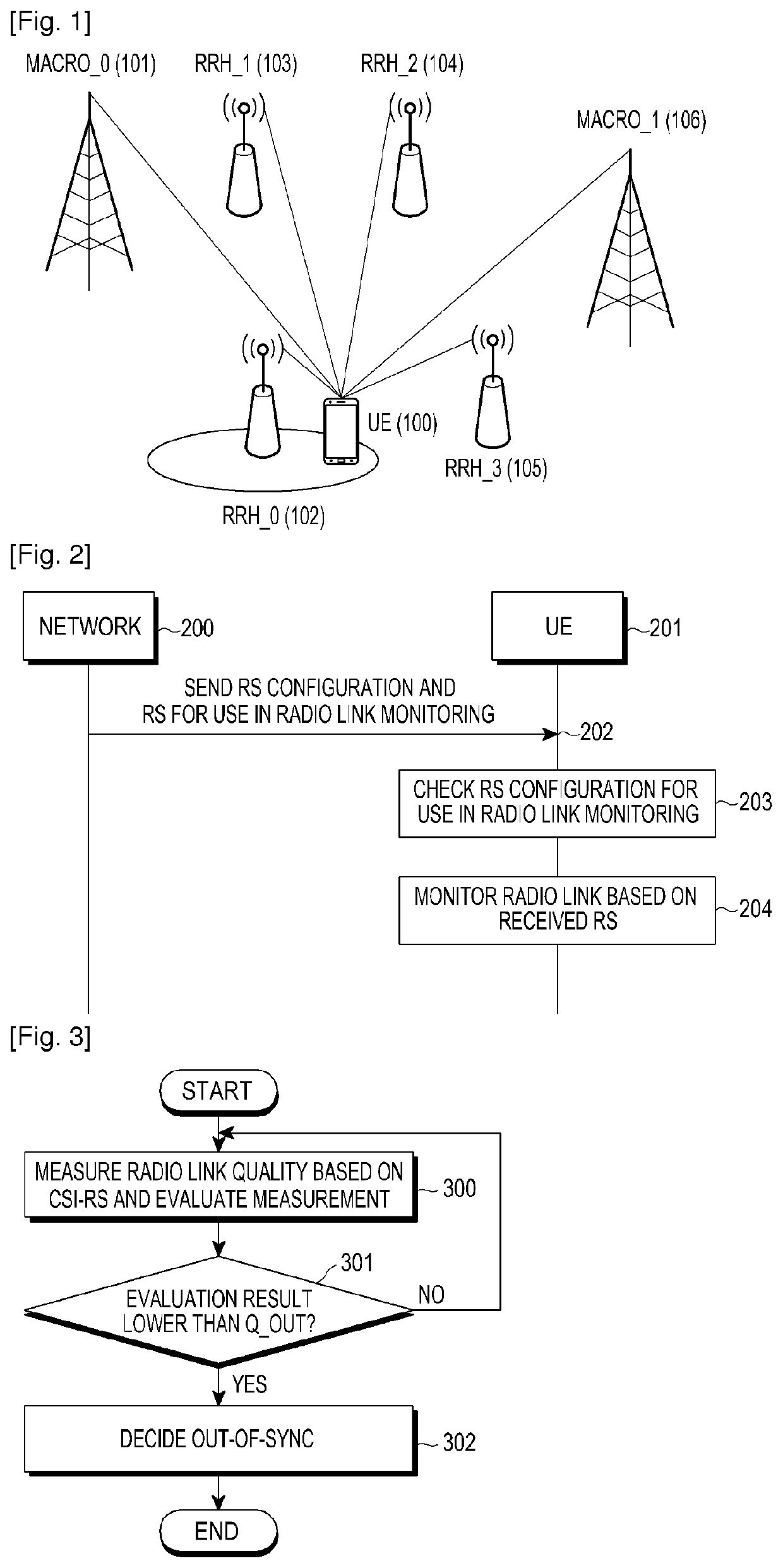
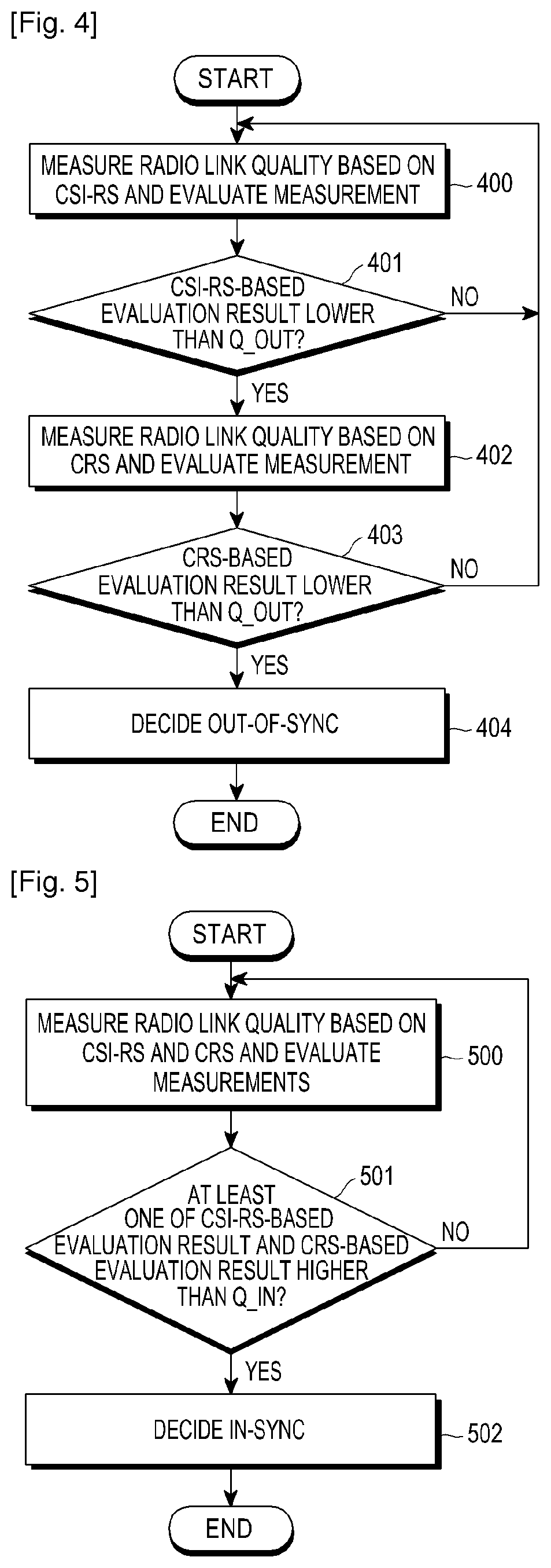
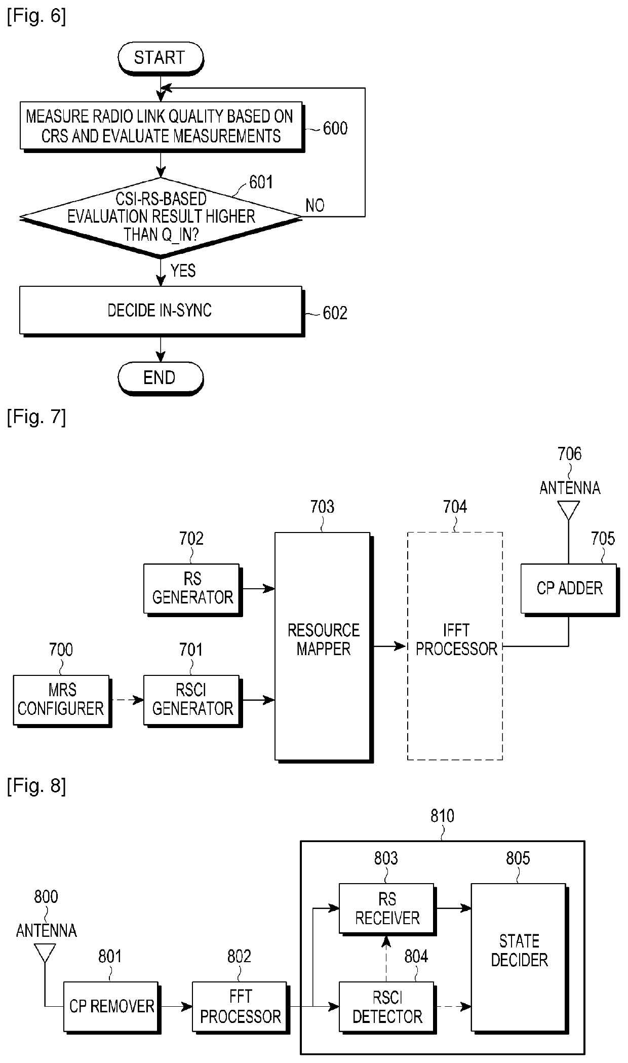
[0035]In embodiments of the present invention as described later, a network configures a Reference Signal (RS) for use in radio link monitoring (hereinafter, referred to as a ‘monitoring RS (MRS)’) and provides configuration information about the MRS (hereinafter, referred to as ‘Reference Signal Configuration Information (RSCI)’) to a User Equipment (UE) in a w...


PUM


Abstract

An apparatus and method for radio link monitoring in a wireless communication system are provided, in which a transmission point communicating with a network where a Base Station (BS) and at least one Remote Radio Head (RRH) coexist within a cell receives Reference Signal Configuration Information (RSCI) from the network to which the transmission point belongs, receives RSs of at least one RS type indicated by the received RSCI from the BS and the at least one RRH that coexist within the cell, and performs radio link monitoring using the received RSs of the at least one RS type.

Description

PRIORITY[0001]This application is a National Stage application under 35 U.S.C. § 371 of International Application No. PCT / KR2012 / 008044 filed Oct. 4, 2012, which claims priority under 35 U.S.C. § 365(b) to Korean Patent Application No. 10-2011-0100628 filed Oct. 4, 2011, the content of each of which is incorporated herein by reference.TECHNICAL FIELD[0002]The present invention relates to an apparatus and method for radio link monitoring in a wireless communication system, and more particularly, to an apparatus and method for monitoring a radio link by selective use of Reference Signals (RSs).BACKGROUND ART[0003]In a wireless communication system, a User Equipment (UE) generally monitors a radio link and evaluates a downlink channel state based on the monitoring result.[0004]For example, the UE measures the channel state of a downlink using an RS received from a network and evaluates the channel quality of the downlink based on the measurement. Then the UE determines whether the down...

Claims


Application Information

Patent Timeline
Patent Type & Authority Patents(United States)
IPC IPC(8): H04W24/02H04W36/00H04W24/04H04W24/08H04W84/04
CPCH04W24/04H04W36/0094H04W24/08H04W84/047H04B17/00H04W88/02
Inventor RO, SANG-MINCHO, JOON-YOUNGKIM, YOUNG-BUMCHOI, SEUNG-HOONKIM, YOUN-SUNLEE, HYO-JINJI, HYOUNG-JU
Owner SAMSUNG ELECTRONICS CO LTD
Why Eureka
Try Eureka