
Television receiver with optical disk reproducing function

a technology of optical disk and receiver, applied in the field of television receiver, can solve the problem of consumption of useless electric power

Inactive Publication Date: 2004-09-02
FUNAI ELECTRIC CO LTD
View PDF9 Cites 14 Cited by
  • Summary
  • Abstract
  • Description
  • Claims
  • Application Information

AI Technical Summary

Benefits of technology

[0016] In this configuration, when a reproduction action of the disk stops with the disk set in the optical disk reproducing means and the operation input is not done for a predetermined time period with the screen saver operating, control is performed so that a power source supply to the receiver stops by the main control means. As a result of this, the amount of electric power equal to that at the time of viewing can be prevented from being consumed while being in a state in which video is not outputted to a display screen and sound is not outputted to a speaker. Further, a power source operation of the optical disk reproducing part can be controlled by the main control means, so that the decision that an abnormal power source stop is made at the time of a power source stop of the optical disk reproducing part as described above can be prevented.
[0020] In this configuration, when a user makes the automatic power source stop function invalid, the automatic power source stop operation described above is not performed and the screen saver continues operating in a disk reproduction stop state. By being configured thus, a power source of the whole receiver can be prevented from stopping automatically without user's intent.

Problems solved by technology

However, even in this state, a power source is supplied to each operation part, so that useless electric power is consumed.
Further, since the fact that the previous end (power source stop) was an abnormal end is outputted to the display screen, a complicated operation for having to check this abnormal end and return to a normal action, etc., had to be performed when the user restarts.

Method used


Image

  • Television receiver with optical disk reproducing function
  • Television receiver with optical disk reproducing function
  • Television receiver with optical disk reproducing function

Examples


Embodiment Construction

[0023] A television receiver with an optical disk reproducing function according to an embodiment of the invention will be described with reference to the drawings.

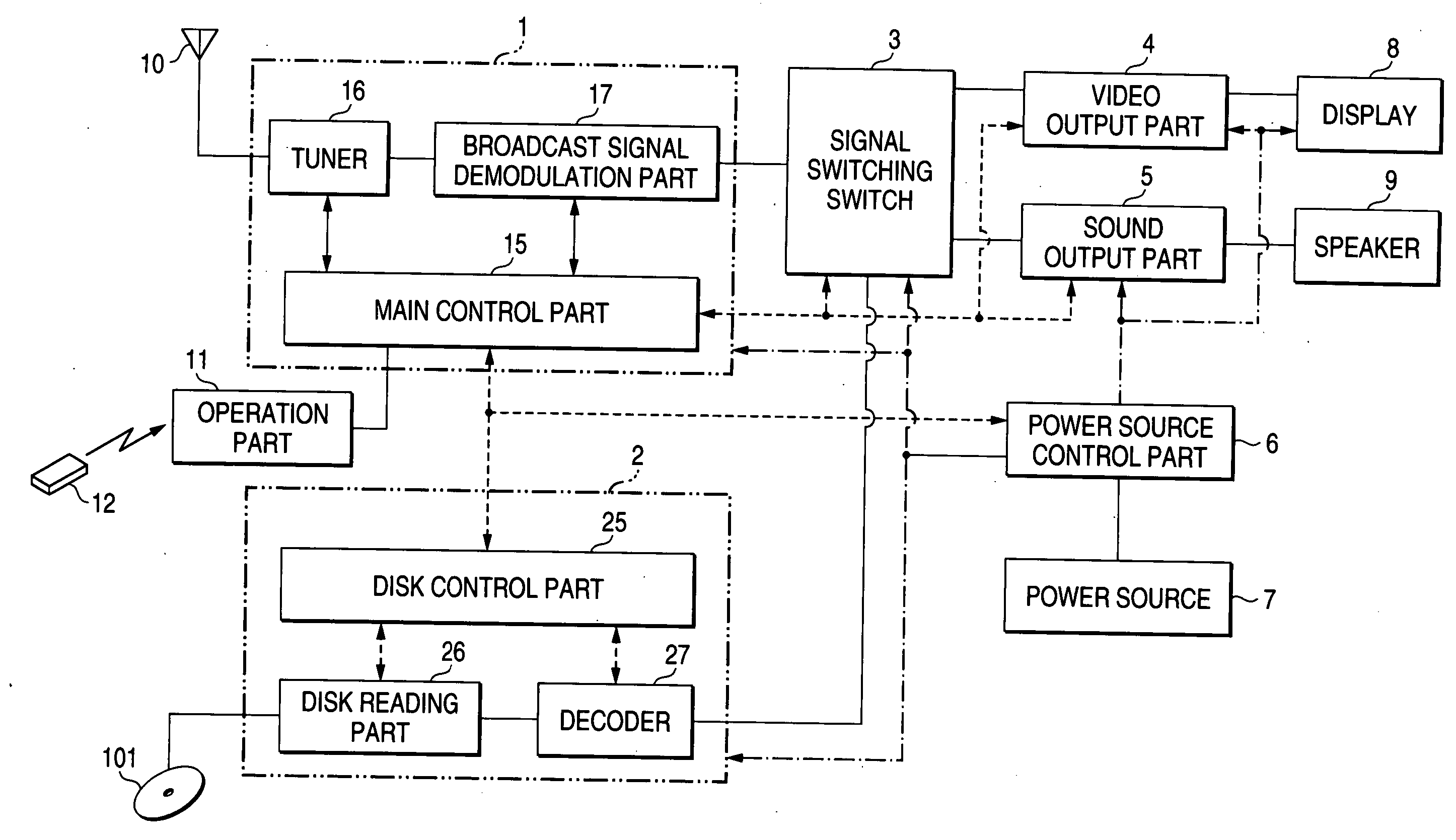
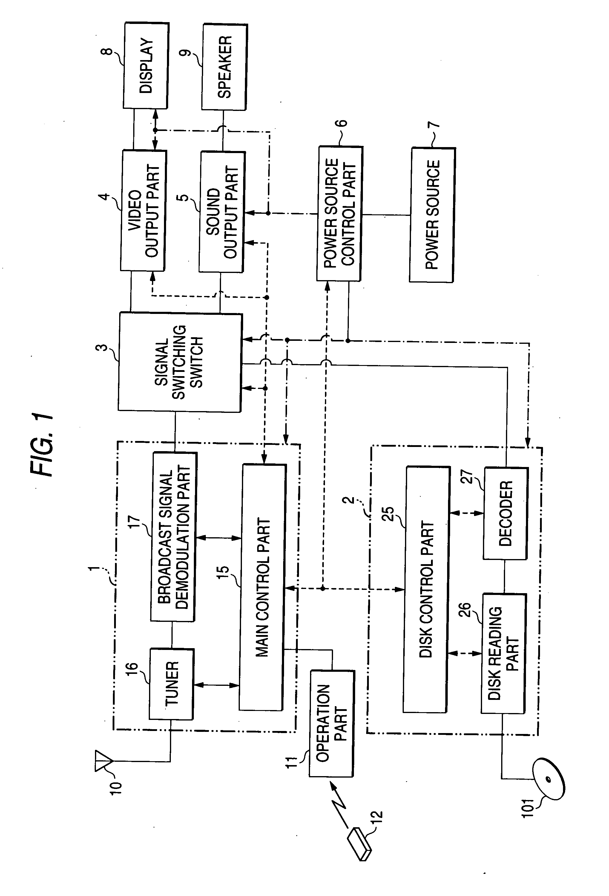
[0024] FIG. 1 is a block diagram showing a main part of a television receiver with an optical disk reproducing function according to the present embodiment.

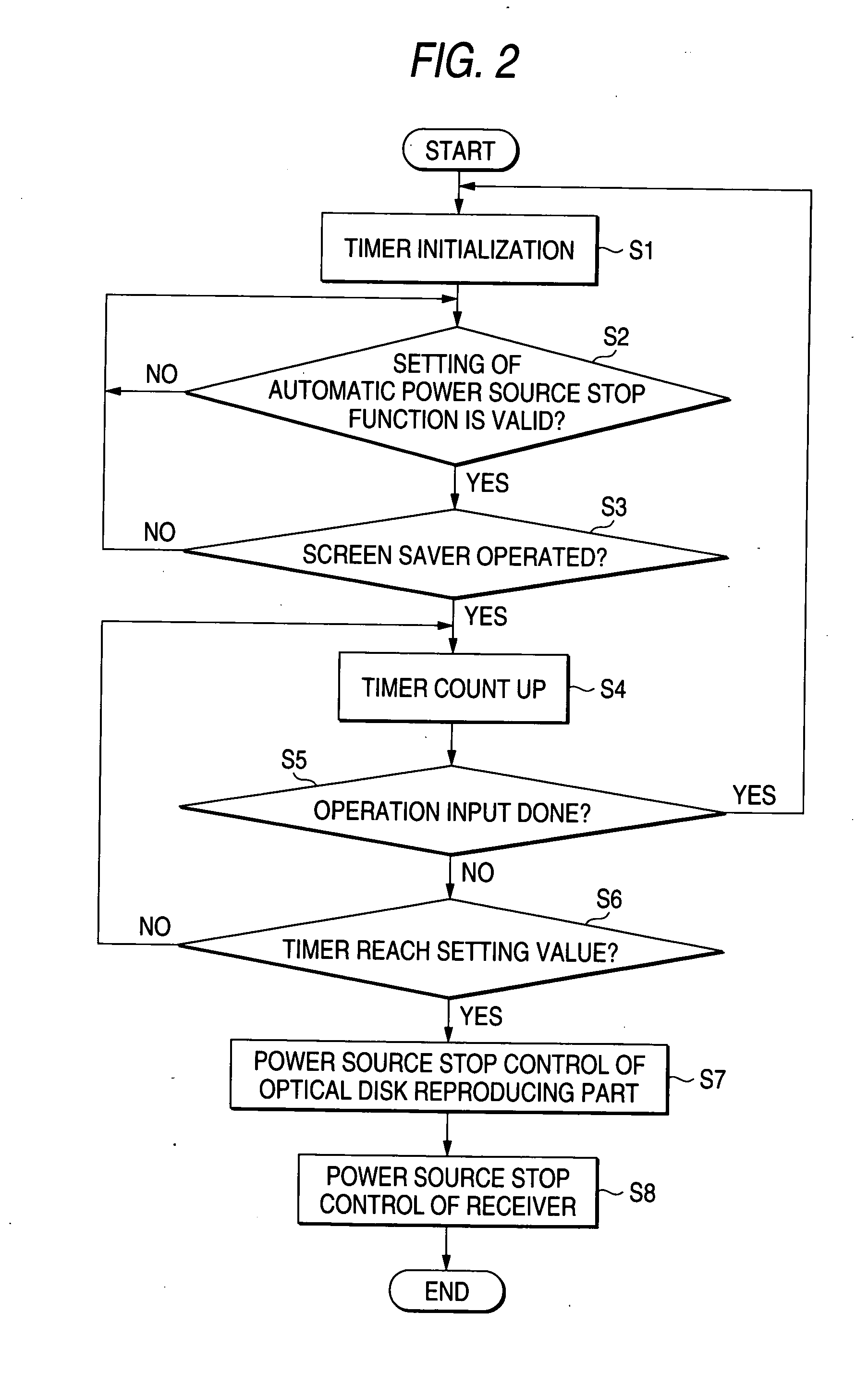
[0025] FIG. 2 is a flowchart showing an action of a main control part at the time of an action of an automatic stop function.

[0026] As shown in FIG. 1, the television receiver with the optical disk reproducing function includes a broadcast signal reproducing part 1, an optical disk reproducing part 2, a signal switching switch circuit 3, a video output part 4, a sound output part 5, a power source control part 6, a power source 7, a display 8, a speaker 9, an operation part 11, and a remote control unit 12.

[0027] The broadcast signal reproducing part 1 includes a tuner 16 for extracting only a broadcast signal of a selected channel among received television broadcast s...


PUM


Abstract

In a television receiver with an optical disk reproducing function, when reproduction of an optical disk ends and stops in an optical disk reproducing part and a screen saver operates, a main control part detects the operation of the screen saver and counts up a timer. When an operation input is not done for a predetermined time period, control is performed so as to stop electric power supply to the optical disk reproducing part. Then, when a power source of the optical disk reproducing part is stopped, the main control part stops power supply to the other parts of the receiver and the receiver shifts to a wait state.

Description

[0001] 1. Field of the Invention[0002] This invention relates to a television receiver equipped with a function of reproducing an optical disk such as a DVD.[0003] 2. Description of the Related Art[0004] A television receiver with an optical disk reproducing function is an apparatus in which a broadcast signal reproducing part for receiving and reproducing a television broadcast signal, an optical disk reproducing part for setting an optical disk and reading out and reproducing video and sound data recorded on the optical disk, and a display screen and a speaker for outputting video and sound reproduced in any of these two reproducing parts are incorporated into an integral cabinet.[0005] In this television receiver with the optical disk reproducing function, when a user makes a selection so as to view a television broadcast using a remote control unit, etc., the broadcast signal reproducing part extracts and demodulates a broadcast signal of a selected channel and projects the vide...

Claims


Application Information

Patent Timeline
Patent Type & Authority Applications(United States)
IPC IPC(8): H04N5/44H04N5/445H04N5/63H04N5/775H04N5/85
CPCH04N5/44H04N5/63H04N5/775H04N21/485H04N21/42646H04N21/4325H04N21/4436H04N5/85
Inventor NISHIGAKI, HIROSHI
Owner FUNAI ELECTRIC CO LTD
Learn More