Free ink writing instrument with microfluidic valve
a writing instrument and microfluidic valve technology, applied in the direction of writing connectors, ink reservoir pens, printing, etc., can solve the problems of significant changes in pressure between the inside and the outside of the ink reservoir, ink may leakage, and the inability of the baffle/porous element/fibrous element to perform the pressure regulating function, so as to avoid solvent evaporation
- Summary
- Abstract
- Description
- Claims
- Application Information
AI Technical Summary
Benefits of technology
Problems solved by technology
Method used
Image
Examples
first embodiment
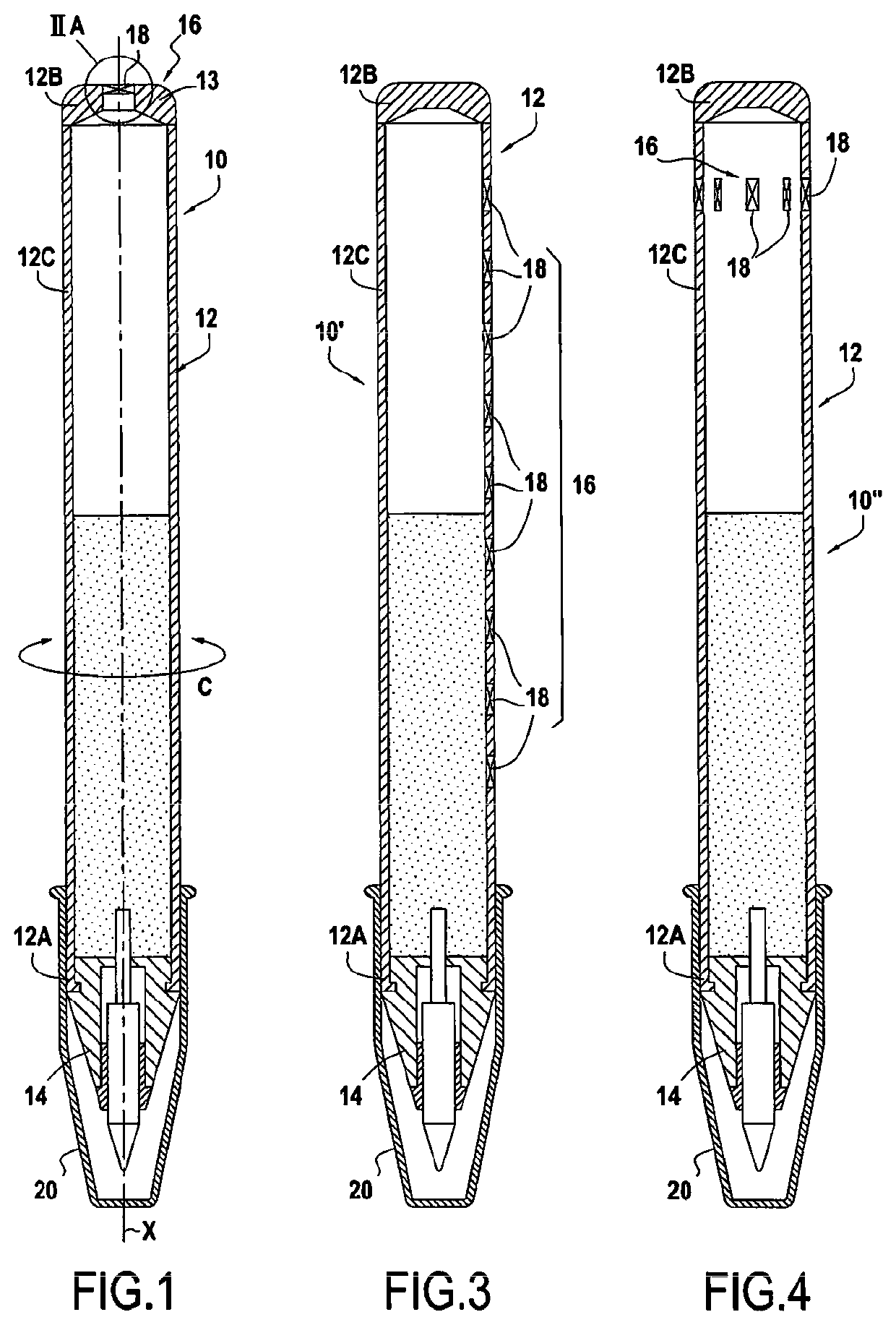
[0052]FIG. 1 shows a writing instrument 10. The writing instrument 10 comprises a main body 12 provided with a writing tip 14. In this embodiment, the main body 12 has an inner cavity and forms a free-ink reservoir 12 in which the ink 13 is free to move. Although the main body and the reservoir are formed by the same part in this embodiment, the main body and the reservoir may be formed by two separate parts in a variant.
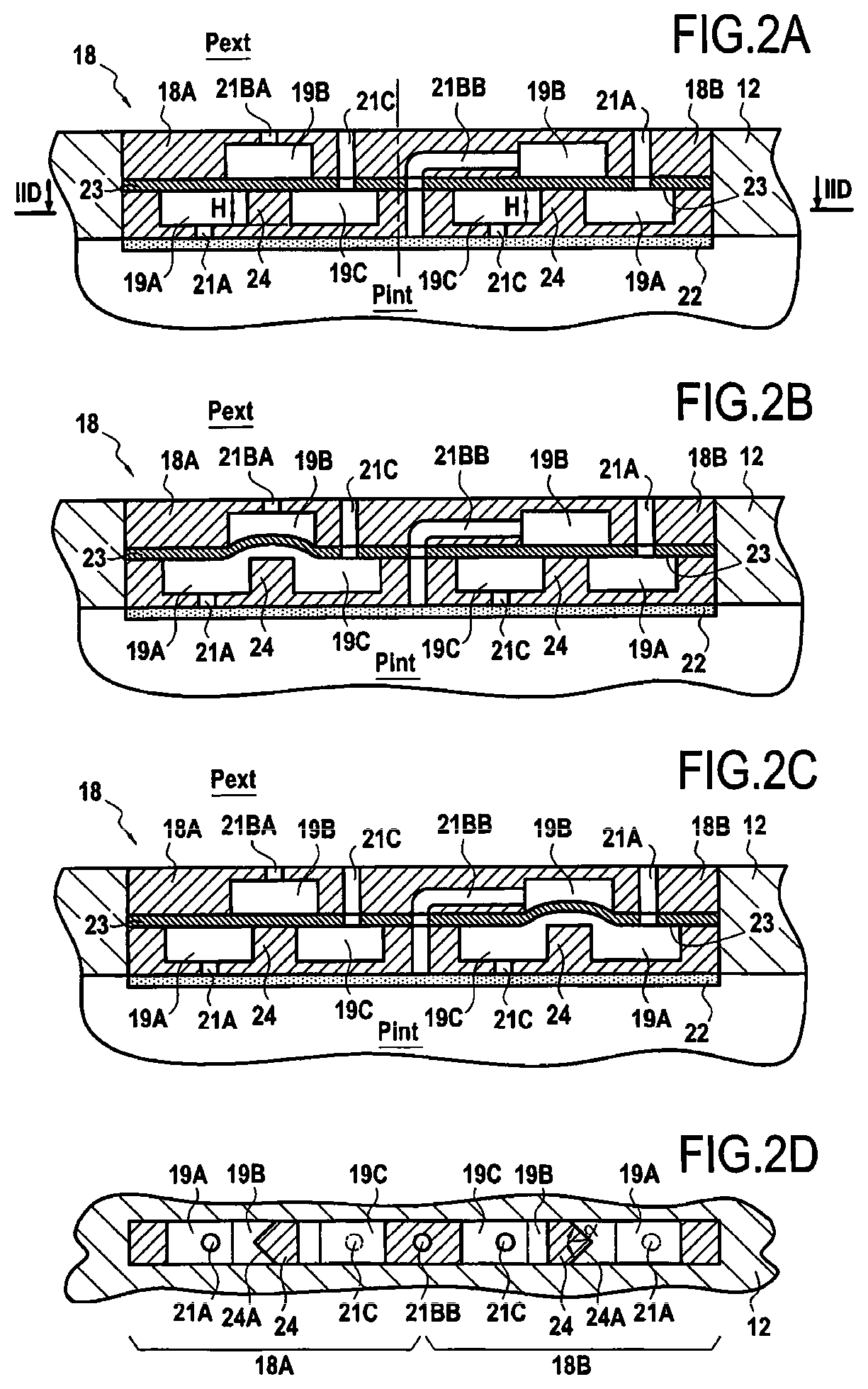
[0053]The reservoir 12 is provided with a pressure regulating device 16 for regulating the pressure within the reservoir 12. In this embodiment, the pressure regulating device 16 comprises a single bidirectional microfluidic-valve unit 18.
[0054]It is noted that the reservoir 12 extends in an axial direction X and a circumferential direction C. The writing tip 14 is arranged at a first end 12A in the axial direction X of the reservoir 12. In this embodiment, the bidirectional microfluidic-valve unit 18 is arranged at the second end of the reservoir 12, opposite the f...
second embodiment
[0066]the writing instrument 10′ in FIG. 3 comprises a plurality of bidirectional microfluidic-valve units 18 evenly distributed in the axial direction X of the reservoir 12. For example, each bidirectional microfluidic-valve unit 18 is spaced apart from the adjacent bidirectional microfluidic-valve units 18 by 1 cm (one centimeter) in the axial direction X.
third embodiment
[0067]the writing instrument 10″ in FIG. 4 comprises a plurality of bidirectional microfluidic-valve units 18 evenly distributed in the circumferential direction C of the reservoir 12. For example, each bidirectional microfluidic-valve unit 18 is spaced apart from the adjacent bidirectional microfluidic-valve units 18 by 36° in the circumferential direction C, around the axis X of the reservoir 12.
PUM
 Abstract
Description
Claims
Application Information
 - R&D
- Intellectual Property
- Life Sciences
- Materials
- Tech Scout
- Unparalleled Data Quality
- Higher Quality Content
- 60% Fewer Hallucinations
Browse by: Latest US Patents, China's latest patents, Technical Efficacy Thesaurus, Application Domain, Technology Topic, Popular Technical Reports.
© 2025 PatSnap. All rights reserved.Legal|Privacy policy|Modern Slavery Act Transparency Statement|Sitemap|About US| Contact US: help@patsnap.com


