
Touch panel and touch display panel

a touch panel and display panel technology, applied in the field of liquid crystal, can solve the problems of poor anti-noise ability, low capacitive touch cost, and inseparable touch devices of smart display devices, and achieve the effect of precise multitouch and strong anti-noise ability

Active Publication Date: 2021-10-05
WUHAN CHINA STAR OPTOELECTRONICS SEMICON DISPLAY TECH CO LTD
View PDF10 Cites 0 Cited by
  • Summary
  • Abstract
  • Description
  • Claims
  • Application Information

AI Technical Summary

Benefits of technology

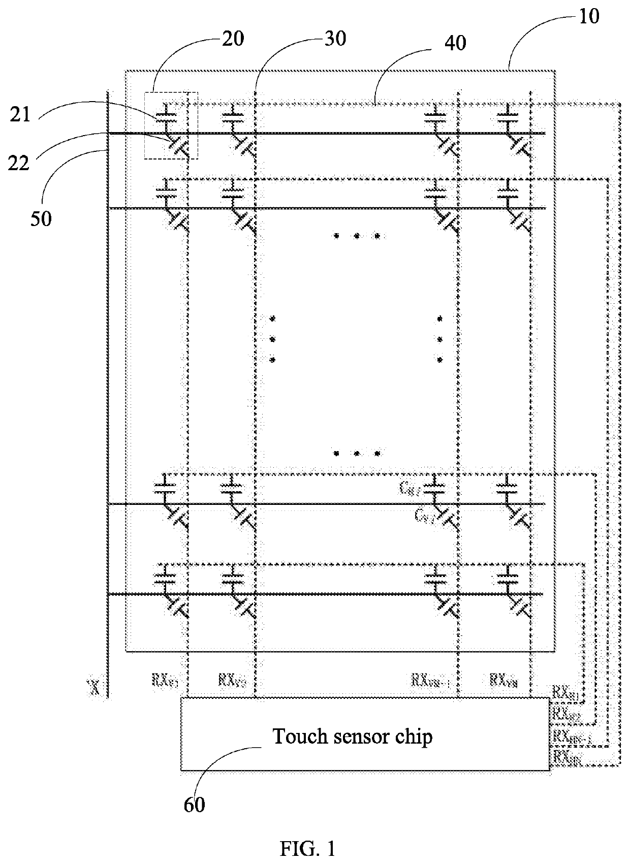
The patent aims to provide a touch panel and touch display panel that can effectively reduce noise and support precise touch detection.

Problems solved by technology

At present, smart display devices are almost inseparable from touch devices.
The self-capacitive touch is low cost and has a simple working mode but poor anti-noise ability.
However, it has the disadvantages of high power consumption and complicated working timing, etc.

Method used


Image

  • Touch panel and touch display panel
  • Touch panel and touch display panel

Examples


Embodiment Construction

[0047]For the purpose of description rather than limitation, the following provides such specific details as a specific system structure, interface, and technology for a thorough understanding of the application. However, it is understandable by persons skilled in the art that the application can also be implemented in other embodiments not providing such specific details. In other cases, details of a well-known apparatus, circuit and method are omitted to avoid hindering the description of the application by unnecessary details.

[0048]In the disclosure, it is should be understood that spatially relative terms, such as “center”, “longitudinal”, “lateral”, “length”, “width”, “above”, “below”, “front”, “back”, “left”, “right”, “horizontal”, “vertical”, “top”, “bottom”, “inner”, “outer”, “clockwise”, “counterclockwise”, “axial”, “radial”, “circumferential”, and the like, may be used herein for ease of description to describe one element or feature's relationship to another element(s) or...


PUM


Abstract

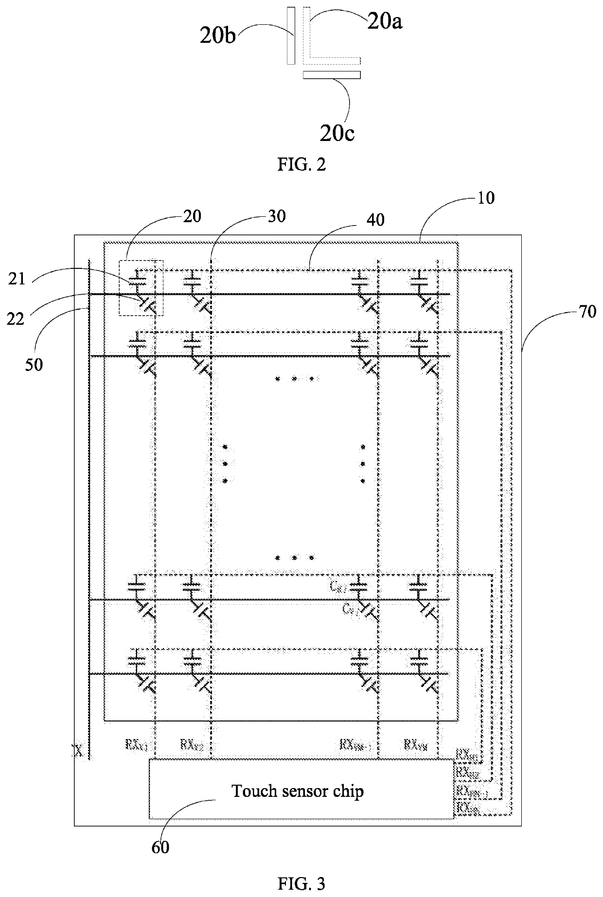
A touch panel includes a substrate, a plurality of capacitive sensor units, an emitting signal line, N first receiving signal lines, and M second receiving signal lines. Each of the capacitive sensor units includes a vertical sensing capacitor and a horizontal sensing capacitor disposed adjacent to each other. The emitting signal line is connected to one terminal of each of the vertical sensing capacitors and one terminal of each of the horizontal sensing capacitors. The N first receiving signal lines, are respectively connected to another terminals of the vertical sensing capacitors of the capacitive sensor units in the N columns. The M second receiving signal lines are respectively connected to another terminals of the horizontal sensing capacitors of the capacitive sensor units in the M rows, the horizontal sensing capacitors in a same row corresponding to one second receiving signal line.

Description

BACKGROUND1. Field of the Invention[0001]The present application relates to the field of liquid crystal, more particularly, to a touch panel and a touch display panel.2. Description of the Related Art[0002]At present, smart display devices are almost inseparable from touch devices. With the development and demand of the market, an increasing number of touch types have emerged. Currently, the most widely used touch technology is capacitive touch, which has the advantages of high transmittance, flexible operation, multi-touch, and long life. Capacitive touch is mainly classified into two types: self-capacitive type and mutual-capacitive type. The self-capacitive touch is low cost and has a simple working mode but poor anti-noise ability. It is easy for multi-touch to generate ghost points. The mutual-capacitive type has strong anti-noise ability and precise multitouch. However, it has the disadvantages of high power consumption and complicated working timing, etc.[0003]Therefore, ther...

Claims


Application Information

Patent Timeline
Patent Type & Authority Patents(United States)
IPC IPC(8): G06F3/041G06F3/044
CPCG06F3/04164G06F3/0446G06F3/044G06F3/0416
Inventor YAN, WEINAN
Owner WUHAN CHINA STAR OPTOELECTRONICS SEMICON DISPLAY TECH CO LTD
Learn More