
Cold gas system for fumigating soil

a technology of cold gas and fumigation process, which is applied in the field of fumigation system, can solve the problems of affecting the effective use affecting the effectiveness of conventional soil fumigation process, and reducing the use of methyl bromide as soil fumigant for agricultural planting sites, so as to achieve improved and more efficient fumigation, effective control of the dispersion of gaseous fumigants

Active Publication Date: 2021-10-19
GODBEHERE JOHN STEPHEN +1
View PDF4 Cites 0 Cited by
  • Summary
  • Abstract
  • Description
  • Claims
  • Application Information

AI Technical Summary

Benefits of technology

The present invention is about a system for fumigating soil which helps to better control the release of gas fumigants from soil. This system improves fumigation efficiency and reduces potential harm to human applicators. Additionally, it does not require water and is useful in areas where water supply is limited.

Problems solved by technology

Due to environmental, health and safety concerns, the use of methyl bromide as a soil fumigant for treating agricultural planting sites has become increasingly restricted.
These gases feature low boiling points and high vapor pressures, which would hinder their effective use in conventional soil fumigation processes.
This produces a refrigeration effect that can cause disruptive freezing in and around the tubing, injection shanks and other equipment used for fumigation.
This problem is, in fact, already encountered with some existing soil fumigants.
Moreover, as highly volatile fumigant gases dissipate from the soil, they can constitute a health hazard that may drift offsite or expose the fumigant applicators.
These methods require the use of large amounts of water.
However, many agricultural fields requiring soil fumigation are located in areas where water usage is limited and / or heavily regulated.
Currently available fumigants can settle out of solution in low areas if they are not properly applied and can severely damage PVC pipes and other components of the irrigation system.
This can be an acute problem when there is a significant dip in the drip irrigation system or an increase in pipe elevation.

Method used


Image

  • Cold gas system for fumigating soil
  • Cold gas system for fumigating soil
  • Cold gas system for fumigating soil

Examples


Embodiment Construction

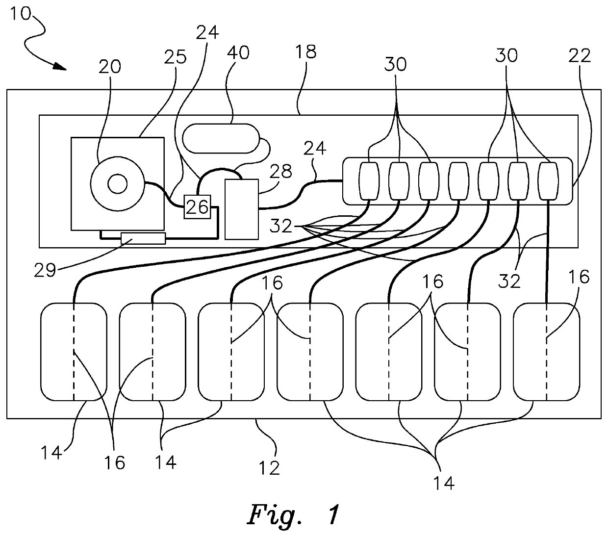
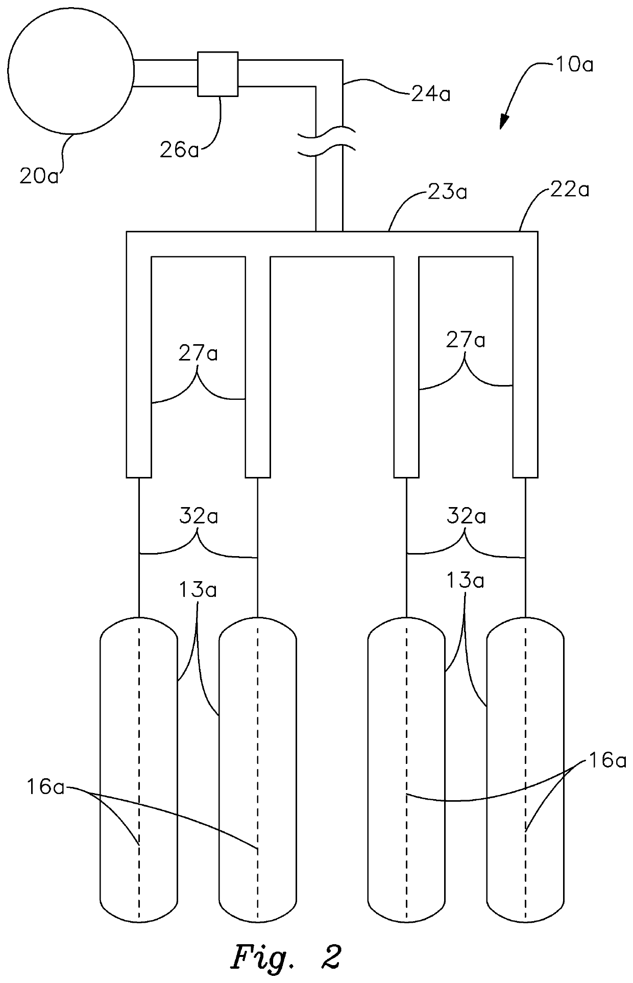
[0028]There is shown in FIG. 1 a system 10 for fumigating the soil of an agricultural field or other planting site 12. The site may feature any variety, shape and / or size of an agricultural field or other site for growing various crops. The size, shape and type of the site and types of crops involved do not constitute limitations of this invention.

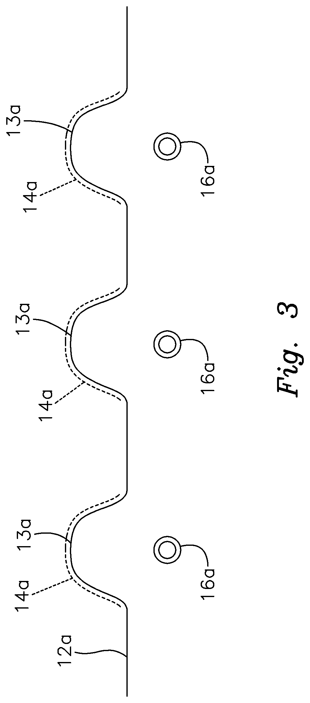
[0029]Site 12 includes a plurality of plant or crop supporting rows or beds covered by respective fumigation film components 14. Each film component may include any one of a variety of different types of bed mulch, broadcast film or fumigation tarp. A preferred material is TIF film of the type that is commonly used in the soil fumigation industry. The length and width of each film component may vary within the scope of this invention. In each case, the fumigation film extends across and covers a respective bed.

[0030]An elongated drip element 16 is disposed beneath each film component 14 and engages the underlying soil of the bed. Each drip...


PUM


Abstract

A system for fumigating soil includes applying a fumigant film component and an underlying drip tape element to the soil to be treated. A non-tarp method can also be used through permanently buried drip tape (SDI) that is at least 8 inches deep and utilizes the soil above as the barrier to prevent the fumigant from escaping. The drip tape element is communicably connected through a throttle valve to a pressurized liquid supply of fumigant having a low boiling point and a high vapor pressure. The valve is opened to dispense vaporized fumigant into the soil and dissipation of the fumigant is controlled so that more effective soil fumigation is achieved.

Description

RELATED APPLICATION[0001]This application claims the benefit of U.S. Provisional Patent Application Ser. No. 62 / 642,242 filed Mar. 13, 2018.FIELD OF THE INVENTION[0002]This invention relates to a system for fumigating soil and, more particularly, to a method and apparatus that utilizes a “cold gas” fumigant having a low boiling point and high vapor pressure to perform soil fumigation more effectively and safely.BACKGROUND OF THE INVENTION[0003]Due to environmental, health and safety concerns, the use of methyl bromide as a soil fumigant for treating agricultural planting sites has become increasingly restricted. Recently, some new compounds, ethanedinitrile (EDN) and sulfuryl fluoride (SF) have been considered as soil fumigant replacements for methyl bromide. These gases feature low boiling points and high vapor pressures, which would hinder their effective use in conventional soil fumigation processes. When standard shank injection is employed, existing fumigants are typically inje...

Claims


Application Information

Patent Timeline
Patent Type & Authority Patents(United States)
IPC IPC(8): A01M13/00A01N25/18A01M17/00
CPCA01M13/00A01M17/002A01N25/18A01M21/04
Inventor GODBEHERE, JOHN STEPHENSTORKAN, DEAN C.
Owner GODBEHERE JOHN STEPHEN
Learn More