
Display device having an eyepiece

a technology of a display device and an eyepiece, which is applied in the direction of instruments, polarising elements, optical elements, etc., can solve the problem of reducing the amount of light emitted to the outside, and achieve the effect of increasing the light extraction efficiency without deteriorating the resolution

Active Publication Date: 2021-11-30
LG DISPLAY CO LTD
View PDF14 Cites 0 Cited by
  • Summary
  • Abstract
  • Description
  • Claims
  • Application Information

AI Technical Summary

Benefits of technology

[0007]An object of the present invention is to provide a display device capable of increasing the light extraction efficiency without the deterioration of the resolution.
[0008]Another object of the present invention is to provide a display device in which a path of light travelling toward an eyepiece from a display panel can be increased, and the loss of the light between the display panel and the eyepiece can be minimized.

Problems solved by technology

However, in the display device of the related art, the amount of the light emitted to the outside can be reduced by the half-mirror, which can cause a problem.

Method used


Image

  • Display device having an eyepiece
  • Display device having an eyepiece
  • Display device having an eyepiece

Examples


embodiments

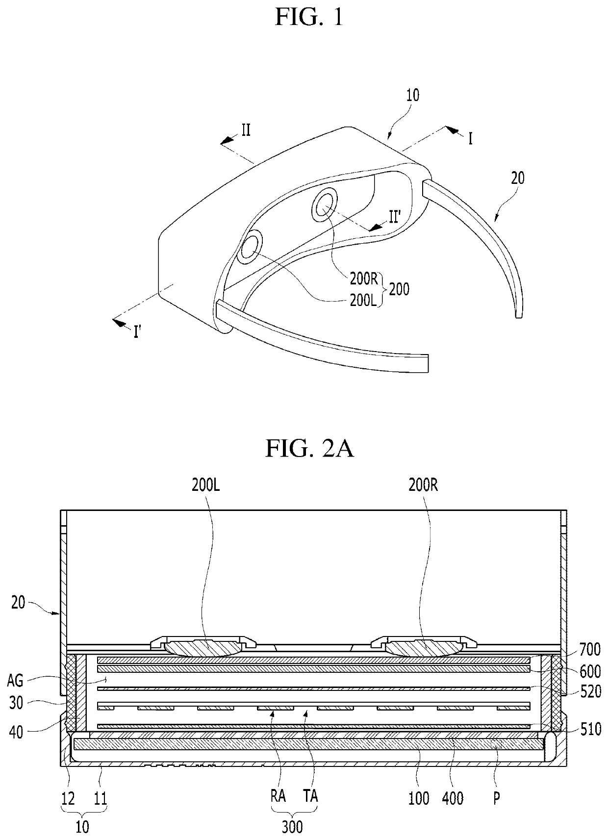
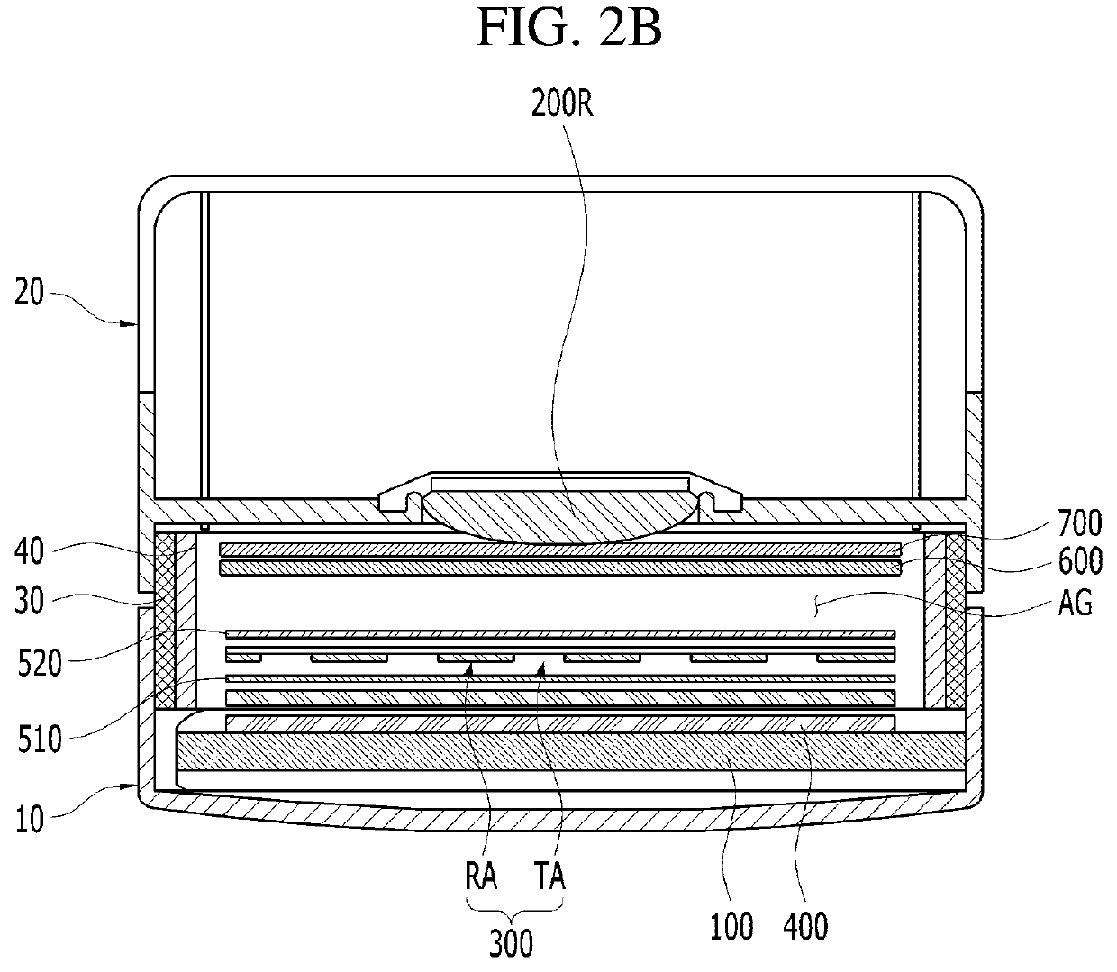
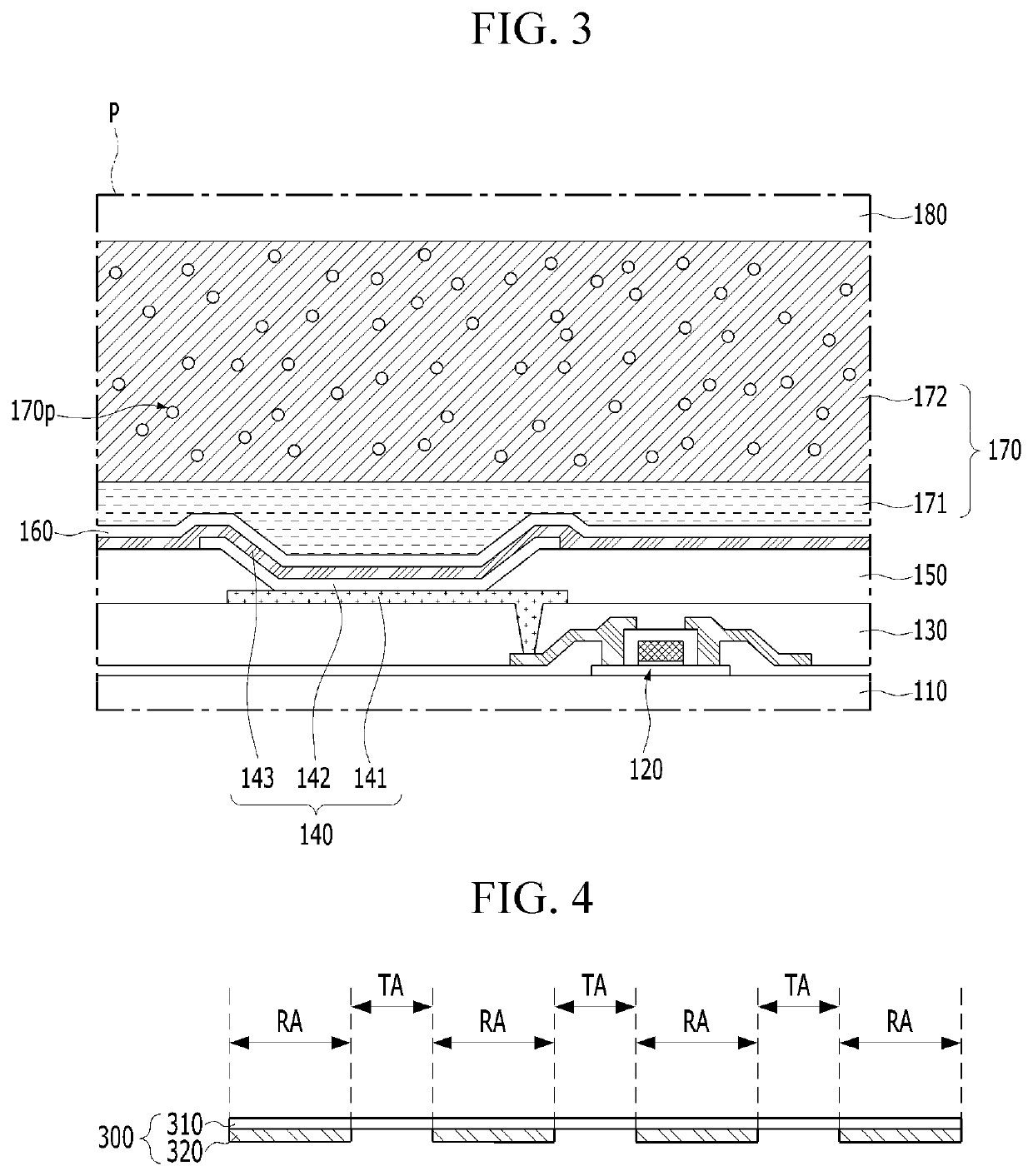
[0037]FIG. 1 is a view schematically showing a display device according to an embodiment of the present invention. FIG. 2A is a view taken along I-I′ of FIG. 1. FIG. 2B is a view taken along II-II′ of FIG. 1. FIG. 3 is an enlarged view of P region in FIG. 2A. FIG. 4 is a view showing a barrier of the display device according to the embodiment of the present invention. FIG. 5 is a view showing the relative location of pixel regions of a display panel and transmitting regions of a barrier in the display device according to the embodiment of the present invention. All the components of the display device according to all embodiments of the present invention are operatively coupled and configured.

[0038]Referring FIGS. 1, 2A, 2B and 3 to 5, the display device according to the embodiment of the present invention can include an image member 10. The image member 10 can realize an image which is provided to a user. For example, the image member 10 can realize an image for a virtual reality (...


PUM


Abstract

A display device including a display panel and an eyepiece is provided. An image realized by the display panel can be provided to a user by passing through the eyepiece. The display device can further include a front quarter-wave plate and a rear quarter-wave plate in order to increase the path of light traveling toward the eyepiece from the display panel. A barrier can be disposed between the front quarter-wave plate and the rear quarter-wave plate. The barrier can reflect or transmit the light traveling toward the eyepiece from the display panel on a region-by-region, so that the loss of light recognized by the user through the eyepiece can be minimized.

Description

CROSS-REFERENCE TO RELATED APPLICATION[0001]This application claims the priority benefit of Korean Patent Application No. 10-2017-0179352, filed on Dec. 26, 2017 in the Republic of Korea, which is hereby incorporated by reference as if fully set forth herein.BACKGROUND OF THE INVENTIONField of the Invention[0002]The present invention relates to a display device in which an image realized by a display panel is provided through an eyepiece.Discussion of the Related Art[0003]Generally, a display device includes a display panel which realizes an image. For example, the display device can include a Liquid Crystal Display (LCD) panel having liquid crystal molecules or an Organic Light-Emitting Diode (OLED) panel having organic light-emitting elements.[0004]The display device can provide an image realized by the display panel to a user through an eyepiece. For example, the display device can be a head mounted display apparatus (HMD) including an image member accommodating the display panel...

Claims


Application Information

Patent Timeline
Patent Type & Authority Patents(United States)
IPC IPC(8): G02B5/30H01L51/52G02B27/28G02B27/01G02B25/00
CPCG02B5/30G02B5/3025G02B5/3083G02B27/0172G02B27/286H01L51/5275G02B25/001G02B2027/0118G02B2027/0178G02B27/28G02B5/22G02B27/022H10K50/858
Inventor PARK, JU-SEONGJUNG, SUNG-MINLEE, KEONG-JIN
Owner LG DISPLAY CO LTD
Learn More