
Neonatal carbon dioxide measurement system

a carbon dioxide and measurement system technology, applied in the field of breath measurement and monitoring, can solve the problems of intrinsic response time of the sensor technology being employed, preventing accurate measurements etc., to achieve accurate measurement of co2 in a breath, disturbing the homogeneity and purity of the different and discrete sections

Active Publication Date: 2021-12-07
CAPNIA INC
View PDF229 Cites 0 Cited by
  • Summary
  • Abstract
  • Description
  • Claims
  • Application Information

AI Technical Summary

Benefits of technology

Enables accurate and reliable CO2 measurement even at high breathing rates by extending the sample duration to match the sensor response time, reducing signal clipping and improving measurement fidelity, thus addressing the limitations of existing capnometry systems.

Problems solved by technology

In current capnometry systems, especially neonatal capnometry, there are two main technical limitations that prevent accurate measurements.
First, the breath sample collection apparatus allows mixing of one section of gas with another section of gas, thus disturbing the homogeneity and purity of the different and discrete sections.
The second problem, which is addressed in the present disclosure, is the intrinsic response time of the sensor technology being employed.
This response time of the sensor is not fast enough to accurately measure the CO2 in a breath when the patient is breathing fast, such as greater than 30 breaths per minute (bpm).
However the sensor signal response is not instantaneous; it can take as long as 400 milliseconds (ms) for the sensor to finish responding to the CO2 molecules in a bolus of gas from a single expiratory cycle.
This technical problem is called clipping of the signal.
Designers can try to extrapolate where the signal would have peaked had the sensor been fast enough, but these extrapolations are inexact, don't take into account the prevailing clinical conditions of the patient, and should not be used in a medical breath test application.
Some manufacturers of capnometry monitors often state that the device is not for neonatal use for this reason.
First, CO2 can be measured in the blood, however, this is invasive and therefore is not a preferred test and is not used for continuous monitoring or repeat testing.
Second, CO2 can be measured transcutaneously, but these systems have not yet been proven to be reliable in all clinical situations.

Method used


Image

  • Neonatal carbon dioxide measurement system
  • Neonatal carbon dioxide measurement system
  • Neonatal carbon dioxide measurement system

Examples


Embodiment Construction

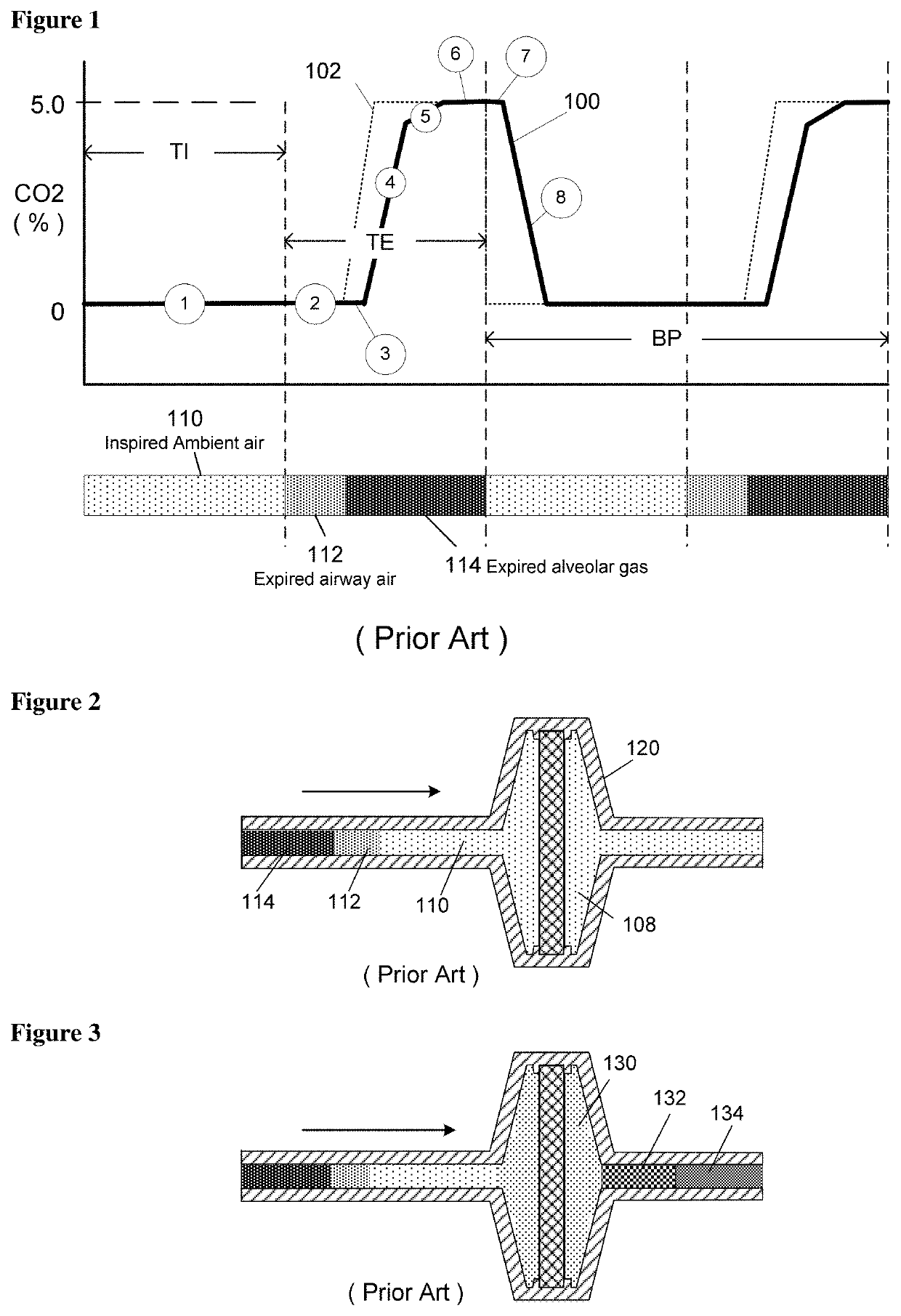
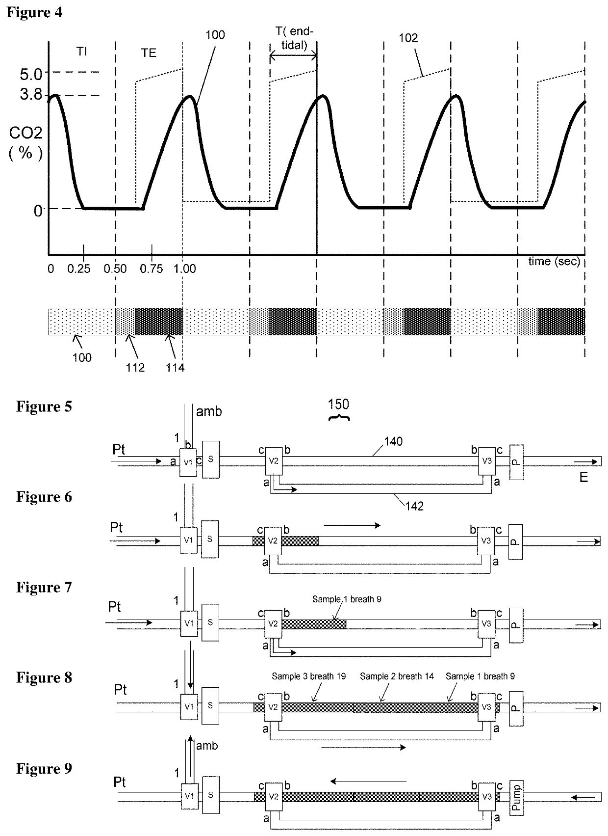
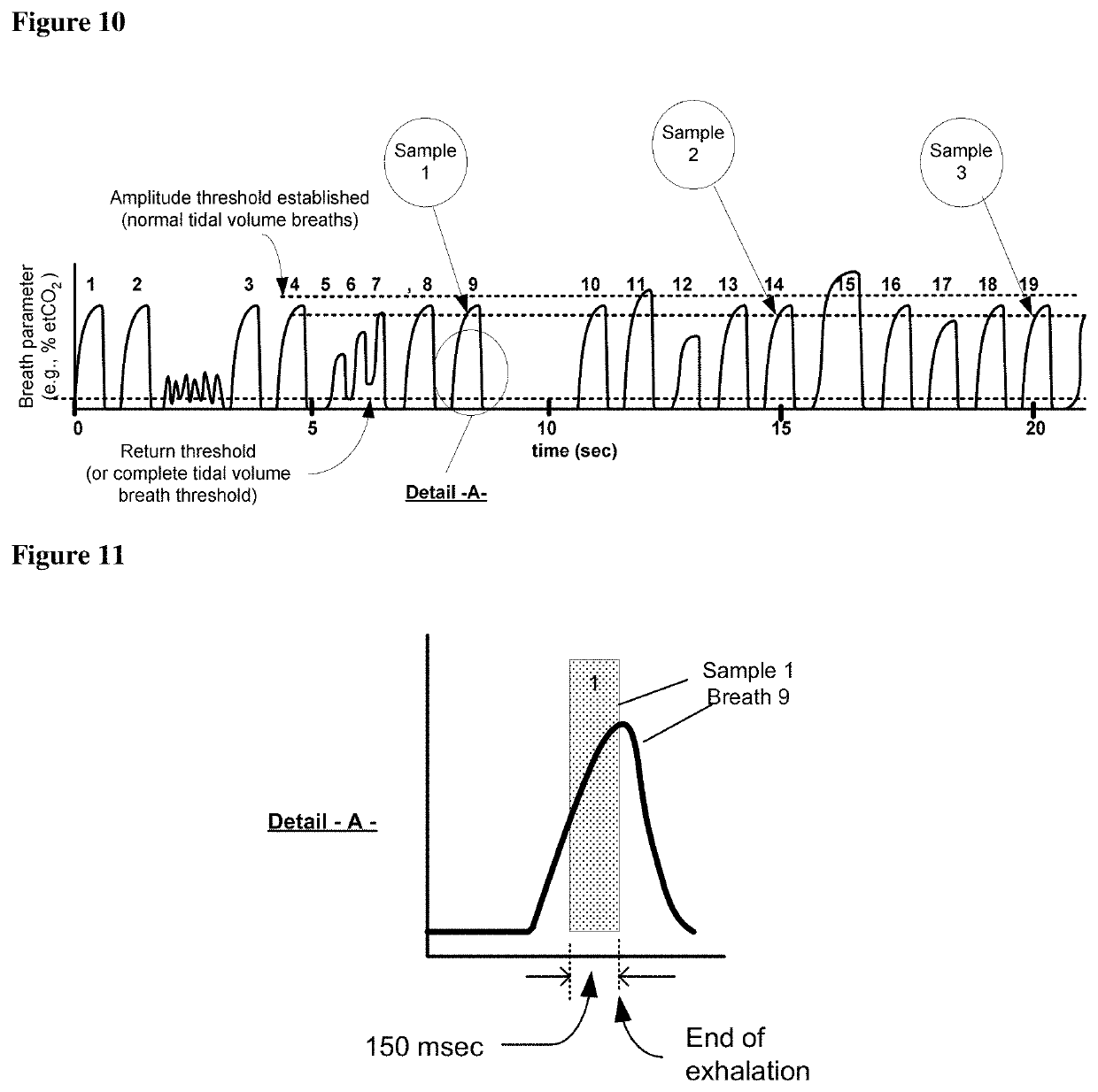
[0031]FIG. 1 graphically describes capnometry, when used for non-infant patients. Typically the breath period (BP), breath rate and expiratory time (TE) is slow enough for the CO2 signal 100 from the capnometry sensor to register the full amplitude of the actual CO2 102 in the breath sample, and an accurate etCO2 result is reported. The capnometry curve can be broken down into 7 parts. The inspiratory part 1 of the breathing curve, during which there is basically no signal response from the Capnometer; the beginning of exhalation 2 during which again there is basically no signal response from the Capnometer; a sensor lag time 3 which is a brief lag period or delay before the sensor responds to the first CO2 gas molecules in the exhalation gas seen by the sensor's sensing element; an increasing signal in the middle of exhalation 4 due to the increasing percentage 5 of CO2 being expelled as gas from deeper in the lung is expelled; a plateau 6 representative of alveolar gas and when th...


PUM

PropertyMeasurementUnit
expiratory timeaaaaaaaaaa
response timeaaaaaaaaaa
exhalation timeaaaaaaaaaa

Abstract

A breath parameter measuring device is described which takes into account breathing patterns which historically have been incompatible with accurate measurements. In particular, during fast breathing patterns, the sensor performing the measurement may not be able to respond quickly enough to provide the true reading. The disclosure may be useful for example in the case of neonatal breath carbon dioxide measurements.

Description

CROSS-REFERENCE TO RELATED APPLICATION[0001]This application claims the benefit of U.S. Provisional Application No. 61 / 872,415, filed Aug. 30, 2013, the content of which is incorporated herein in its entirety.FIELD OF THE INVENTION[0002]The present Disclosure applies to the field of breath measurements and monitoring and specifically to the field of measuring a constituent in the exhaled gas of a patient for the purpose of monitoring the patient's condition.BACKGROUND[0003]In various breath parameter measurement applications, the current state-of-the-art measurement technology may not provide an accurate or reliable measurement during fast breathing patterns because the response time of the sensor employed is not fast enough to measure the breath parameter. Such measurement applications may be those in which continuous monitoring is desired, or in which intermittent monitoring is desired, or in which a one-time breath test is desired. In capnometery for example, Infra-Red sensors ar...

Claims


Application Information

Patent Timeline
Patent Type & Authority Patents(United States)
IPC IPC(8): A61B5/083A61B5/08A61B5/097G01N33/497
CPCA61B5/0836A61B5/0816A61B5/097G01N33/497
Inventor WONDKA, ANTHONY D.BHATNAGAR, ANISHDE LA SERNA, PEDRO E.
Owner CAPNIA INC
Learn More