Tail bearing housing

a bearing housing and tail bearing technology, applied in the direction of engines, machines/engines, gas turbine plants, etc., can solve the problems of high manufacturing cost and damage to the construction of composite materials, and achieve the effect of minimising noise and reducing bleed air and the flow of the core engin

Active Publication Date: 2021-12-07
ROLLS ROYCE PLC
View PDF12 Cites 0 Cited by
  • Summary
  • Abstract
  • Description
  • Claims
  • Application Information

AI Technical Summary

Benefits of technology

[0033]In general, the bleed air may be vented parallel to the core engine flow, so shear between the bleed air and the core engine flow may be minimised, thereby minimising noise.

Problems solved by technology

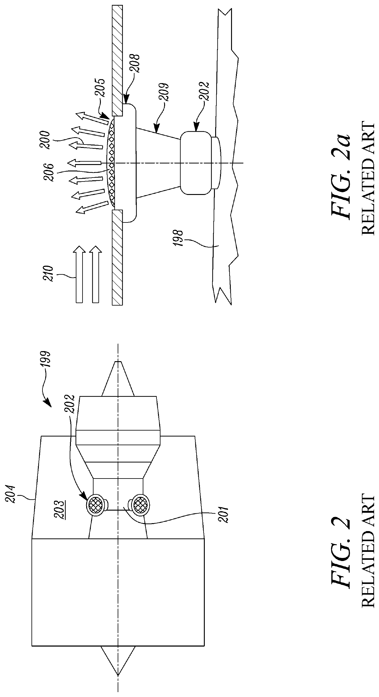
As the bleed air 200 has high kinetic energy and high temperature, problems can arise where the high energy and high temperature bleed air 200 impinges directly onto the bypass duct walls 204 which can quickly cause damage to the composite material construction.
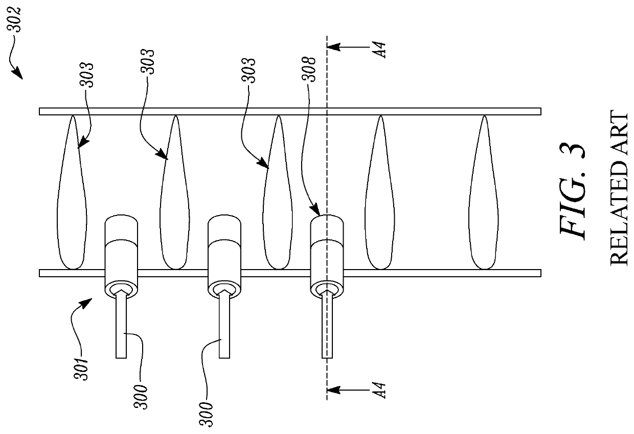
Attenuators and seals can be provided, but are costly to manufacture.

Method used


Image

  • Tail bearing housing
  • Tail bearing housing
  • Tail bearing housing

Examples


first embodiment

[0077]In a first embodiment illustrated in FIGS. 8-9a, the vent vane 115 is provided with one first aperture 116 and a plurality of second apertures 117.

[0078]The second apertures 117 are in form of slots, arranged along the trailing edge 110 and extending spanwise. In other words, the second apertures 117 feature a slot-shaped transversal cross-section, extending in spawise direction.

[0079]The second apertures 117 are so shaped to vent bleed air 119 parallel to the core engine flow 129 downstream of the vanes 108. In the first embodiment of FIG. 8-9a, the second apertures 117 extend linearly and parallel to the core engine flow 129 at the trailing edge 110.

[0080]FIGS. 10 and 10a show a second embodiment of vent vanes 115. The components of FIGS. 10 and 10a are substantially identical to the components of the first embodiment of FIGS. 8-9a, except as otherwise described below.

[0081]The vent vane 115 comprises a plurality of second apertures 117 in form of spanwise extending slots si...

third embodiment

[0087]Although illustrated in FIG. 12a only with reference to the forth embodiment, the vent vanes 115 of each of the first, second and third embodiment may comprise the septum 125 to define corresponding first and second chambers 126, 127.


PUM


Abstract

A tail bearing housing of a turbomachine comprises an inner casing and an outer casing concentrically arranged along a longitudinal axis, and a plurality of vanes having a leading edge, a trailing edge, a first wall extending from the leading edge to the trailing edge and a second wall extending from the leading edge to the trailing edge, the first wall and the second wall defining an aerofoil, the vanes being connected at a first end to the outer casing and at a second end to the inner casing. At least one vane of the plurality of vanes is a vent vane comprising a first aperture arranged in the first end and a second aperture arranged in the aerofoil, the second aperture being configured to be in fluid communication with the first aperture through an inner cavity to vent bleed air.

Description

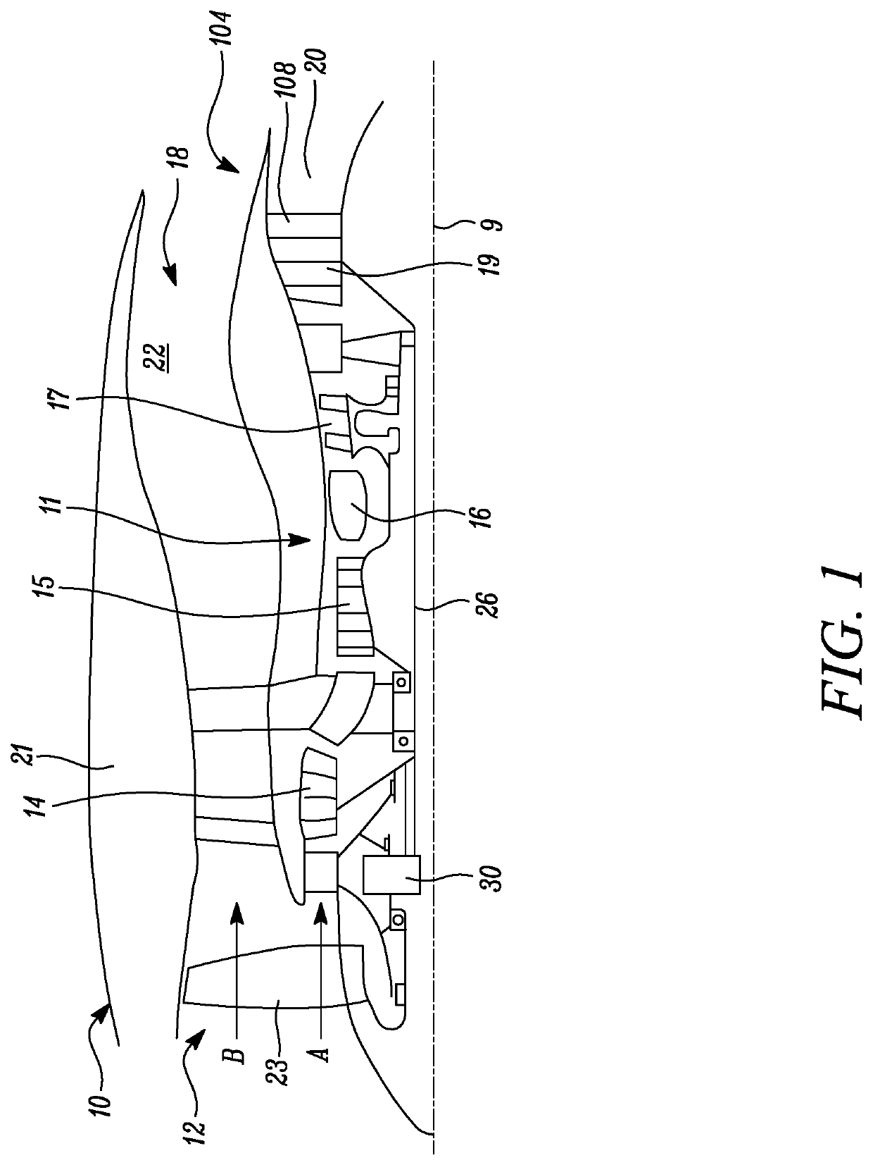
CROSS-REFERENCE TO RELATED APPLICATIONS[0001]This specification is based upon and claims the benefit of priority from UK Patent Application Number 1801956.2 filed on 7 Feb. 2018, the entire contents of which are incorporated herein by reference.BACKGROUNDField of the Disclosure[0002]The present disclosure relates to a tail bearing housing, and in particular to a tail bearing housing for bleeding air in gas turbine engines.Description of the Related Art[0003]A gas turbine engine generally comprises, in axial flow series, an air intake, a fan, one or more compressors, a combustor, one or more turbines, and an exhaust nozzle. Air entering the air intake is accelerated by the fan to produce two air flows: a first air flow (core engine flow) into compressor and a second air flow (bypass flow) which passes through a bypass duct to provide propulsive thrust. Air entering the compressor is compressed, mixed with fuel and then fed into the combustor, where combustion of the air / fuel mixture ...

Claims


Application Information

Patent Timeline
Patent Type & Authority Patents(United States)
IPC IPC(8): F01D9/06F01D25/16F01D25/30F01D9/04F02C9/18F02K3/06
CPCF01D9/06F01D9/041F01D9/065F01D25/162F01D25/30F02C9/18F02K3/06F05D2220/323F05D2240/12F05D2260/606
Inventor GOULDS, ROBERT
Owner ROLLS ROYCE PLC
Why Eureka
Try Eureka