Methods and apparatus for communicating via digital subscriber lines

a technology of digital subscriber and communication method, applied in the direction of subscriber line interface circuit, line-transmission details, electrical apparatus, etc., can solve the problems of increasing the start-up (and restart) time of dsl system, reducing the effectiveness of lines carrying high bandwidth signals, and reducing service interruptions experienced, so as to reduce the amount of initialisation time, reduce operator costs, and reduce service interruptions

Active Publication Date: 2022-01-04
BRITISH TELECOMM PLC
View PDF23 Cites 1 Cited by
  • Summary
  • Abstract
  • Description
  • Claims
  • Application Information

AI Technical Summary

Benefits of technology

[0056]Preferred embodiments of the invention can significantly reduce the amount of time taken to initialise and add one or more DSL lines into an existing group of vectored lines. This can be of benefit to end-user experience particularly when a connection is temporarily dropped and needs to be re-initialised, for example, and also has the potential to reduce costs for operators by reducing service interruptions experienced by end-users.

Problems solved by technology

However, a problem with using high-frequency signals is that a phenomenon known as “cross-talk” can cause significant interference, reducing the effectiveness of lines to carry high bandwidth signals in situations where there is more than one metallic pair carrying similar high-frequency signals in close proximity to one another.
In simple terms, the signals from one pair can “leak” onto a nearby line (which may be carrying similar signals) and appear as noise to the other line.
Start-up (and restart) time is an increasing problem for DSL systems.
The time taken is related mainly to processing power in the DSLAM, and may also be influenced by the amount of additional noise in the process with more lines.
This is because the process of estimation is generally not perfect.
Each channel of crosstalk cancelled may be imperfect, leaving some residual noise.
Due to limited precision at all stages in the process and environmental noise on all lines, the more lines are included, the longer time the probe sequences will have to be transmitted in order to estimate the crosstalk coupling coefficients through the inherent noise in the system.

Method used


Image

  • Methods and apparatus for communicating via digital subscriber lines
  • Methods and apparatus for communicating via digital subscriber lines
  • Methods and apparatus for communicating via digital subscriber lines

Examples


Embodiment Construction

[0062]With reference to the accompanying figures, methods and apparatus according to preferred embodiments will be described.

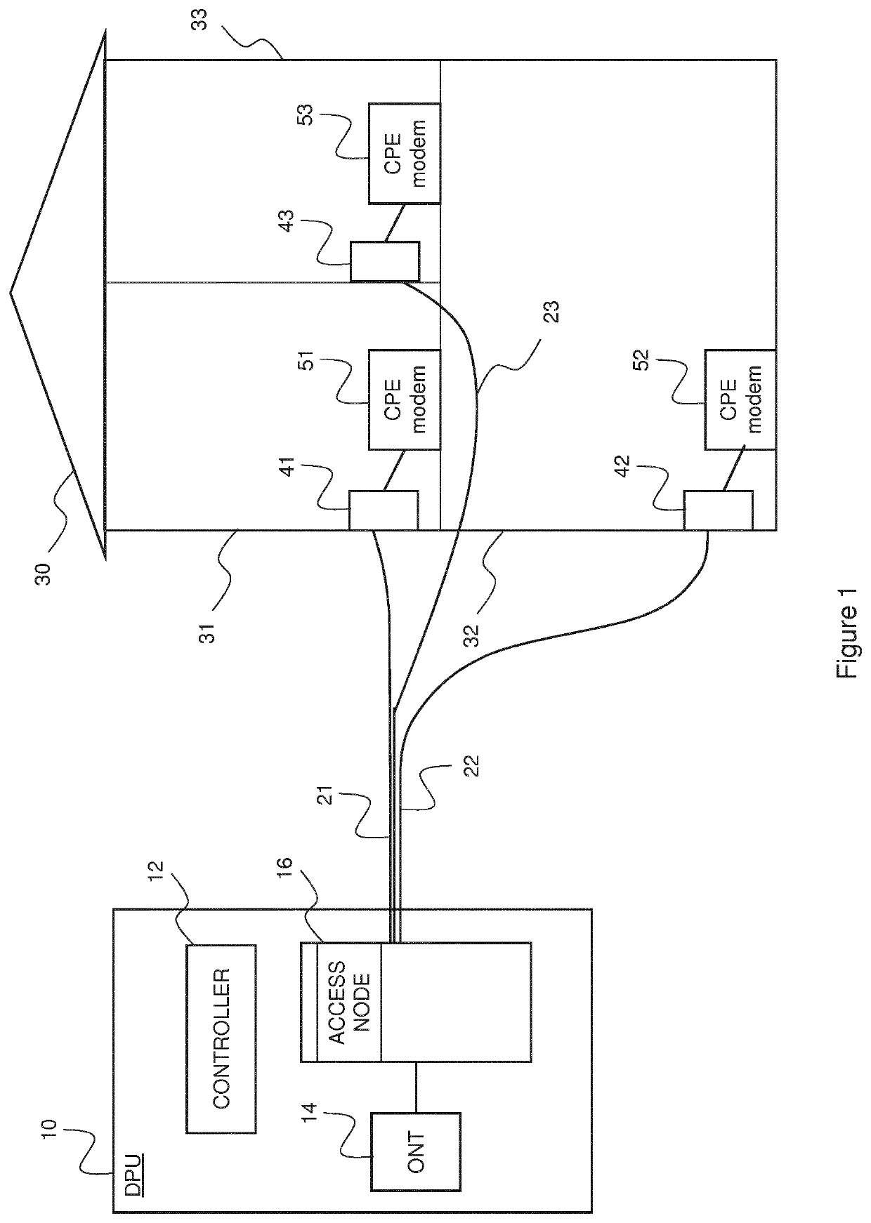
[0063]Firstly, an example broadband deployment in which embodiments of the present invention could be employed will be illustrated in overview with reference to FIG. 1. As shown in FIG. 1, the example deployment comprises a Distribution Point Unit (DPU) 10 which is connected to three user premises 31,32, 33 (which in this example are shown as rooms or flats within a single house 30) via respective Twisted Metallic Pair (TMP) connections 21, 22, 23 which connect between an Access Node (AN) 16 (e.g. a Digital Subscriber Line Access Multiplexor (DSLAM)) within the DPU 10 and respective Customer Premises Equipment (CPE) modems 51, 52, 53 via respective network termination points 41, 42, 43 within the respective customer premises 31, 32, 33. The DPU 10 additionally includes an Optical Network Termination (ONT) device 14 which provides a backhaul connection from the...


PUM


Abstract

Methods and apparatus are disclosed for communicating in a telecommunication system. In particular methods and apparatus are disclosed for establishing communications in a telecommunication system having an access node (16) and a plurality of Digital Subscriber Lines (DSLs) (21, 22, 23) each of which may be used to allow communication between the access node (16) and a respective Customer Premises Equipment (CPE) device (51, 52, 53), where communications on a plurality of lines (21, 21) are being performed using vectoring, and where it is desired to add one or more new lines (23) to the existing vectoring group.

Description

[0001]This application is the U.S. national phase of International Application No. PCT / EP2019 / 072354 filed Aug. 21, 2019 which designated the U.S. and claims priority to EP Patent Application No. 18190111.7 filed Aug. 21, 2018, the entire contents of each of which are hereby incorporated by reference.TECHNICAL FIELD[0002]The present invention relates to methods and apparatus for communicating in a telecommunication system, and in particular to methods and apparatus for establishing communications in a telecommunication system having an access node and a plurality of Digital Subscriber Lines (DSLs) each of which may be used to allow the transmission of data from a transmitter device to one or more receiver devices, the transmission of data involving transmission of data signals over metallic conductors such as pairs of wires. Such methods include all of the various Digital Subscriber Line (DSL) methods as specified in various International Telecommunications Union (ITU) standards and...

Claims


Application Information

Patent Timeline
Patent Type & Authority Patents(United States)
IPC IPC(8): H04M3/00H04M11/06
CPCH04M3/007H04M11/062H04B3/32
Inventor HORSLEY, IAN
Owner BRITISH TELECOMM PLC
Why Eureka
Try Eureka