Image reading apparatus
a technology of image reading and reading cylinder, which is applied in the direction of thin material processing, article separation, printing, etc., can solve the problems of irregularities in the edges of those sheets, and achieve the effect of avoiding irregularities and avoiding irregularities
- Summary
- Abstract
- Description
- Claims
- Application Information
AI Technical Summary
Benefits of technology
Problems solved by technology
Method used
Image


Examples
first embodiment
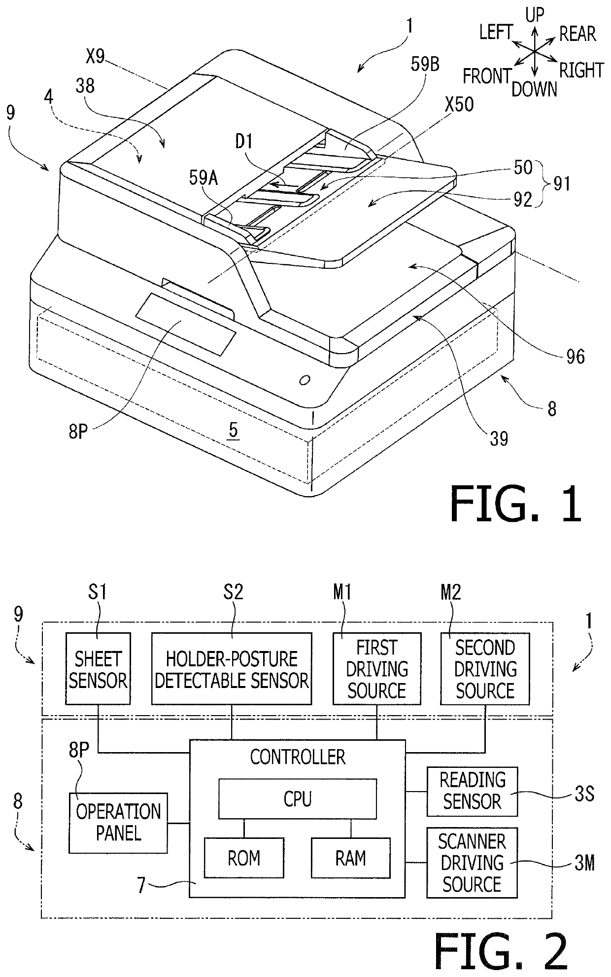
[0020]FIG. 1 shows an image reading apparatus 1 according to the first embodiment of the present disclosure. As shown in FIG. 1, positional relation within the image reading apparatus 1 and each part or item included in the image reading apparatus 1 will be mentioned on basis of the orientation of the image reading apparatus 1 as indicated by arrows in FIG. 1. For example, a side, on which an operation panel 8P is arranged, is defined as a front side of the image reading apparatus 1, and a side opposite to the front side is defined as a rear side. A right-hand side and a left-hand side to a user who faces the front side of the image reading apparatus 1 are defined as a rightward side and a leftward side, respectively. Moreover, a right-to-left or left-to-right direction may be called as a crosswise direction, a front-to-rear or rear-to-front direction may be called as a front-rear direction, and a direction orthogonal to the crosswise direction and to the front-rear direction may be...
second embodiment
[0101]As shown in FIG. 8, an image reading apparatus in the second embodiment of the present disclosure may be different from the image reading apparatus 1 described in the first embodiment in that a pressing device 70 is provided on an upper face of the holder 42F.
[0102]The pressing device 70 includes a pressing lever 71 and a compressed coil spring 72. The pressing lever 71 is swingably supported by the holder 42F at one end thereof, and the other end of the pressing lever 71 may contact an inner or downward surface of the cover member 38 from below. The compressed coil spring 72 is arranged between the holder 42F and the pressing lever 71 and applies an urging force that may separate the pressing member 71 from the holder 42F to the pressing member 71. The pressing device 70 in this configuration may urge the holder 42F so that the holder 42F tends to pivot downward, and feed roller 41 supported by the holder 42F the holder 42F may be urged against the sheets SH supported on the ...
third embodiment
[0114]As shown in FIG. 11, an image reading apparatus in the third embodiment of the present disclosure may be different from the image reading apparatus with the pressing device 70 in the second embodiment in that a thickness detector 75 is provided.
[0115]The thickness detector 75 includes a sensor supporting portion 76, a thickness sensor 78, and a compressed coil spring 77. The sensor supporting portion 76 is swingably supported by the cover member 38 at one end thereof, and the other end of the sensor supporting portion 76 may contact the uppermost sheet SH in the sheets SH supported on the feed tray 91 from above. The thickness sensor 78 is retained at the other end of the sensor supporting portion 76. The thickness sensor 78 may be, for example, an ultrasonic sensor that emits ultrasonic waves at the sheets SH stacked on the feed tray 91, receives the waves reflected on the sheets SH, and detects the thickness of the sheets SH based on the received waves. The compressed coil s...
PUM
| Property | Measurement | Unit |
|---|---|---|
| thickness | aaaaa | aaaaa |
| angles | aaaaa | aaaaa |
| shape | aaaaa | aaaaa |
Abstract
Description
Claims
Application Information
PatSnap Eureka turns technology decisions into work you can execute. Powered by our Innovation Knowledge Graph, it runs expert workflows across engineering, life sciences, materials and intellectual property. Get your review-ready output in minutes.


