Method for controlling an aircraft, and an aircraft (variants)

a multi-boom aircraft and control method technology, applied in aircrafts, aircraft health monitoring devices, transportation and packaging, etc., can solve the problems of aircraft damage, aircraft wing exposure to loads, bending and torsion deformation, etc., and achieve the effect of reducing the complexity of manufacturing and control, and reducing the number of aircra

Active Publication Date: 2022-03-15
MIRA AEROSPACE LTD
View PDF10 Cites 0 Cited by
  • Summary
  • Abstract
  • Description
  • Claims
  • Application Information

AI Technical Summary

Benefits of technology

[0058]The advantage of the tandem arrangement in comparison with the first embodiment of the invention is in an improved structural rigidity. Severe external impacts on one of the wings (1, 1′) caused by elastic nature of structural components will be extended to the second one of the wings (1, 1′). The aircraft will be more resistant to destructive external actions. This is why at a given design strength, the rigidity requirements to each of the wings (1, 1′) and, accordingly, to a weight of the wings (1, 1′) can be reduced to some extent.

Problems solved by technology

When in operation, the aircraft wing is exposed to loads and experiences bending and torsion deformations.
However, if the wing of such aircraft is rigid, in-flight loads produced by aerodynamic disturbance can provoke destruction of the aircraft.
The drawback of this configuration is an insufficient strength of materials to be used and complexity of manufacturing and control.

Method used


Image

  • Method for controlling an aircraft, and an aircraft (variants)
  • Method for controlling an aircraft, and an aircraft (variants)
  • Method for controlling an aircraft, and an aircraft (variants)

Examples


first embodiment

[0050 of the present invention.

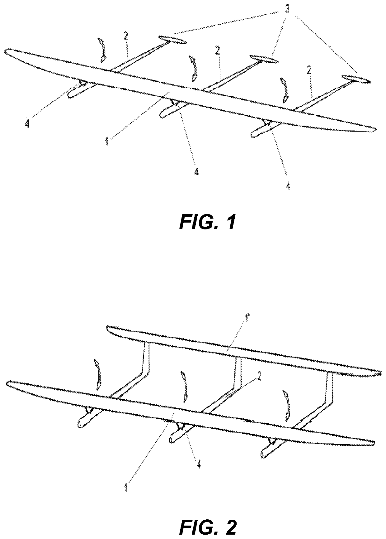
[0051]FIG. 1 shows one of the preferred embodiments of the invention. Here, a wing (1) is connected to booms (2), or fuselages, arranged transversely to the wing (1). In accordance with this embodiment of the invention, a horizontal tail (3) including a fixed stabilizer is mounted on each of the booms (2).

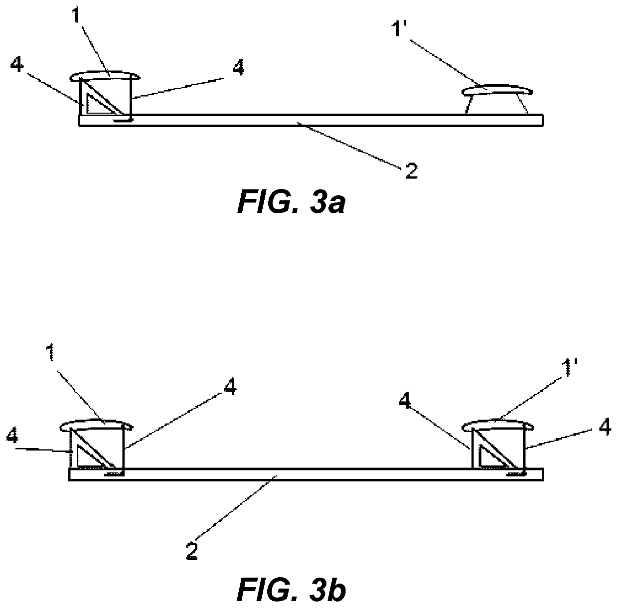
[0052]The wing (1) is connected to the booms (2) and configured to be pivotal, by means of actuators (4), with at least a portion thereof about an axis extending along a line of a span of the wing (1). Possible pivoting directions are shown in FIG. 1 by arrows. The actuators (4) are mounted on the booms (2) and can be brought into action by servomotors or other drivers well known to one skilled in the art.

[0053]The optimal number of the booms (2) is at least three, whereas the wing (1) is connected to each of the booms (2) by means of the corresponding actuator (4). The actuators (4) are made such that they can be operated independently from each othe...

second embodiment

[0056 of the present invention.

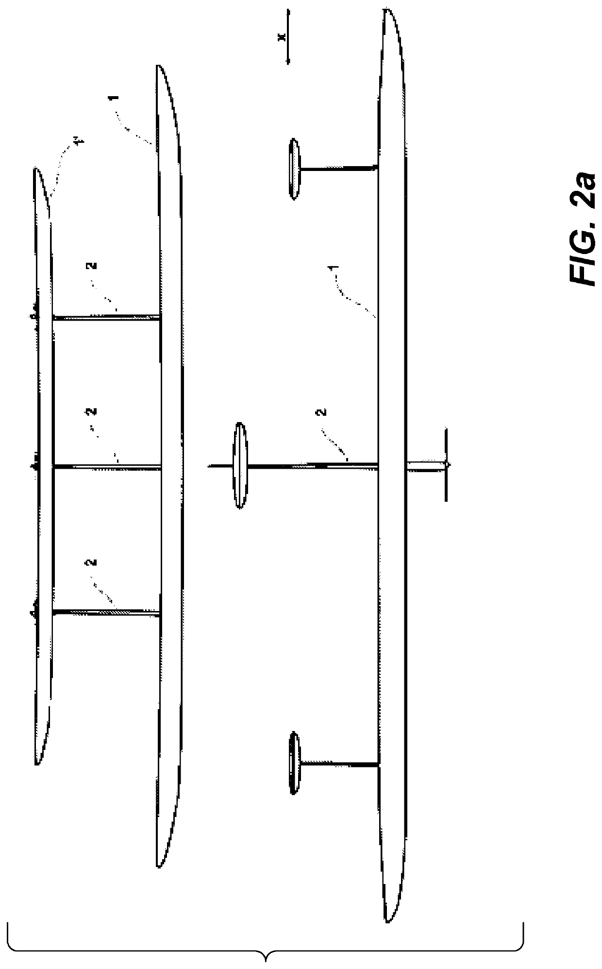
[0057]FIG. 2 shows another preferred embodiment of the invention. Here, dimensions of a horizontal tail surface are such that this surface can be mounted on all booms (2) at once and this surface substantially is a second wing (1′) arranged backward of and parallel to a first wing (1). In this way, a tandem arrangement of the aircraft is formed. The second wing (1′) can be exactly the same as the first wing (1) or can have dimensions, profile, etc. different from those of the first wing (1).

[0058]The advantage of the tandem arrangement in comparison with the first embodiment of the invention is in an improved structural rigidity. Severe external impacts on one of the wings (1, 1′) caused by elastic nature of structural components will be extended to the second one of the wings (1, 1′). The aircraft will be more resistant to destructive external actions. This is why at a given design strength, the rigidity requirements to each of the wings (1, 1′) and, ...


PUM


Abstract

A multi-boom aircraft with an adjustable wing geometric twist includes at least one wing, and at least three booms arranged transversely to at least one of the wings. Each of the booms includes at least one actuator, and the at least one wing is mounted on the booms so as at least a portion of the corresponding wing can be pivoted by means of the actuators about an axis extending substantially along the corresponding wing.

Description

FIELD OF THE INVENTION[0001]The present invention relates to methods for controlling a multi-boom aircraft which uses a wing to generate a lift, to methods of changing a wing geometric twist of such aircraft, and to a design of such aircraft.PRIOR ART[0002]One of the critical parameters of an aircraft is the lift-to-drag ratio, that is, the amount of lift generated by a wing, divided by the drag it creates at a given angle of attack. The lift-to-drag ratio has an impact on aircraft performances, such as gliding range, flight range, and endurance, fuel consumption, climbing performances, etc.[0003]The more the wing aspect ratio is, the more the lift-to-drag ratio increases. Thus, the lift-to-drag ratio of an aircraft, and therefore aircraft performances, can be increased by increasing the wing aspect ratio as much as possible.[0004]The wing aspect ratio has the main role for the use of an aircraft as so-called atmospheric satellites, (atmosat, pseudo-satellite). These are high-altitu...

Claims


Application Information

Patent Timeline
Patent Type & Authority Patents(United States)
IPC IPC(8): B64C3/38B64C3/52B64C39/04
CPCB64C3/385B64C3/52B64C39/04B64C39/08B64D2045/0085Y02T50/10
Inventor BATURA, TSIMAFEITYTSYK, YURYSTRATSILATAU, ALIAKSEISHPILEUSKI, VIACHASLAU
Owner MIRA AEROSPACE LTD
Why Eureka
Try Eureka