Check patentability & draft patents in minutes with Patsnap Eureka AI!

Pallet, pallet stacking system and pallet stacking method

a technology of pallets and stacking methods, applied in the field of pallets, can solve the problems of increasing the cost of accurately stacking pallets, and achieve the effects of high accuracy, high accuracy, and increased cos

Active Publication Date: 2022-03-15
TOYOTA JIDOSHA KK
View PDF13 Cites 0 Cited by
  • Summary
  • Abstract
  • Description
  • Claims
  • Application Information

AI Technical Summary

Benefits of technology

[0006]In view of such an issue, the present disclosure realizes a pallet, a pallet stacking system, and a pallet stacking method that can accurately stack the pallet while suppressing an increase in cost.
[0017]According to the present disclosure, it is possible to realize a pallet, a pallet stacking system and a pallet stacking method that can accurately stack a pallet while suppressing an increase in cost.

Problems solved by technology

The technique described in JP 2018-58679 A requires the use of a plurality of two-dimensional distance meters for adjusting the stacking position of the pallet disposed in the upper stage, and thus the cost increases in order to stack the pallet accurately.

Method used


Image

  • Pallet, pallet stacking system and pallet stacking method
  • Pallet, pallet stacking system and pallet stacking method
  • Pallet, pallet stacking system and pallet stacking method

Examples


first embodiment

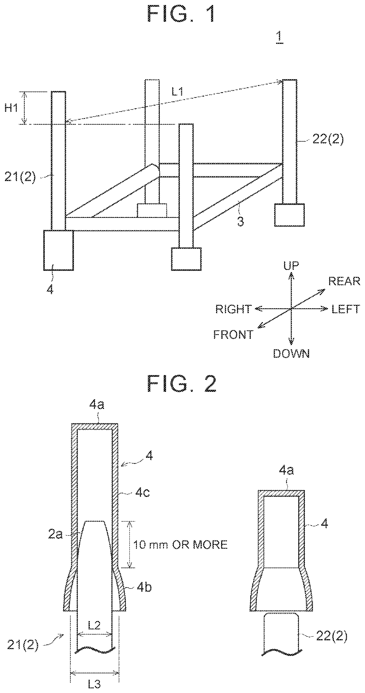
[0042]First, the configuration of the pallet according to the present embodiment will be described. The following description is made based on a state where the pallet is placed on a horizontal surface. Further, the following description is made based on the up-down direction, the front-rear direction, and the right-left direction shown in FIG. 1, but the front-rear direction and the right-left direction may be appropriately replaced with each other depending on the arrangement of the pallets.

[0043]FIG. 1 is a perspective view showing a pallet according to the present embodiment. FIG. 2 is a diagram showing the relationship between the height of the upper end portion of the column of the pallet disposed in the lower stage and the depth of the inserted portion provided in the lower end portion of the column of the pallet disposed in the upper stage.

[0044]A pallet 1 of the present embodiment is suitable for stacking and arranging work pieces in a facility such as a warehouse, for exam...

second embodiment

[0081]In the first embodiment, an operator operates the forklift 5 to stack the pallet 1, but the pallet 1 may be stacked using a self-propelled moving body. First, the configuration of a stacking system 31 for the pallet 1 according to the present embodiment will be described.

[0082]FIG. 6 is a side view showing how the upper end portion of the first column is detected by a detection unit provided in a moving body in a pallet stacking system according to the present embodiment. FIG. 7 is a plan view showing how the upper end portion of the first column is detected by the detection unit provided in the moving body in the pallet stacking system according to the present embodiment. FIG. 8 is a block diagram showing a control system of the moving body in the pallet stacking system according to the present embodiment. Note that in FIGS. 6 and 7, a laser beam emitted from the detection unit is shown by a long dashed double-short dashed line. Further, in FIG. 7, the hatched portion indicat...

third embodiment

[0102]FIGS. 10A to 10D are diagrams showing how the pallet according to the present embodiment is stacked. FIGS. 11A to 11D are diagrams showing how the upper end portion of the column of the second pallet is inserted into the inserted portion of the first pallet.

[0103]A pallet 6 in the present embodiment also has a configuration in which, as shown in FIG. 10D and the like, the upper end portions of columns 7 of the pallet disposed in the lower stage (hereinafter may be referred to as a second pallet 62) are inserted into inserted portions 9 provided in the lower end portions of the columns 7 of the pallet disposed in the upper stage (hereinafter may be referred to as a first pallet 61), such that the pallet 6 can be stacked in the up-down direction.

[0104]Specifically, as shown in FIG. 10A and the like, the pallet 6 includes the columns 7, beams 8, the inserted portions 9, and a cup 10, and for example, the pallet 6 is assembled into a rectangular frame structure when viewed in the ...


PUM


Abstract

A pallet that is stackable in an up-down direction in which upper end portions of a plurality of columns of a pallet disposed in a lower stage are inserted into inserted portions provided in lower end portions of columns of a pallet disposed in an upper stage. A height of at least one column is higher than heights of other columns.

Description

CROSS-REFERENCE TO RELATED APPLICATION[0001]This application claims priority to Japanese Patent Application No. 2020-096753 filed on Jun. 3, 2020, incorporated herein by reference in its entirety.BACKGROUND1. Technical Field[0002]The present disclosure relates to a pallet, a pallet stacking system, and a stacking method, and for example, specifically relates to a pallet that can be stacked in the up-down direction in which the upper end portions of a plurality of columns of the pallet disposed in the lower stage are inserted into the inserted portions provided in the lower end portions of the pallet disposed in the upper stage, a pallet stacking system, and a stacking method.2. Description of Related Art[0003]Generally, a pallet has a configuration in which the upper end portions of a plurality of columns of the pallet disposed in the lower stage are inserted into the inserted portions provided in the lower end portions of the pallet disposed in the upper stage, such that the pallet...

Claims


Application Information

Patent Timeline
Patent Type & Authority Patents(United States)
IPC IPC(8): B65D19/00B65D19/38
CPCB65D19/385B65D2519/0097B65D2519/00542B65D21/023B65D19/06B65D2519/00273B65D2519/00323B65D2519/00338B65D2519/00701B66F9/0755
Inventor ASAMI, DAISUKEIHARA, TOMOAKISHIGEMASA, TAKUMI
Owner TOYOTA JIDOSHA KK
Features
  • R&D
  • Intellectual Property
  • Life Sciences
  • Materials
  • Tech Scout
  • Unparalleled Data Quality
  • Higher Quality Content
  • 60% Fewer Hallucinations
Learn More