
Armrest of vehicle seat

a technology for vehicle seats and armrests, which is applied in the direction of armrests, vehicle components, vehicle arrangements, etc., can solve the problems of increased weight, deterioration of the comfort of the seat back, and increased thickness of the armrests and armrests

Active Publication Date: 2022-03-29
TOYOTA BOSHOKU KK
View PDF8 Cites 0 Cited by
  • Summary
  • Abstract
  • Description
  • Claims
  • Application Information

AI Technical Summary

Benefits of technology

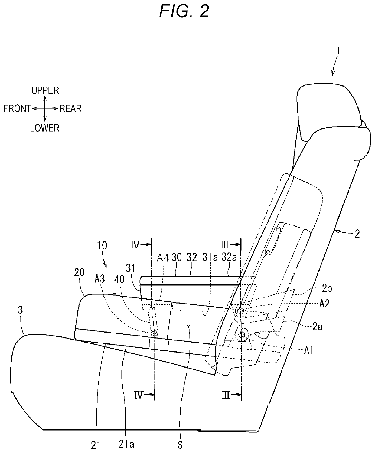
[0010]According to the first aspect, the second armrest is close to the rear side of the first armrest in the storage position of the first armrest and is separated upward from the first armrest in the use position of the first armrest, so as to implement a function of the armrest. In this manner, the armrest can be compactly stored while maintaining the comfort of use and accordingly, the substantial volume of the entire armrest can be reduced and an increase in weight can be prevented.
[0012]According to the second aspect, the seat back, the first armrest, the second armrest, and the first link member constitute a four-bar link. Since this structure requires only the first link member in addition to the first armrest and the second armrest, the second armrest can be interlocked to the first armrest with a simple structure.
[0014]According to the third aspect, this structure requires only the second link member in addition to the first armrest and the second armrest. Accordingly, the second armrest can be interlocked to the first armrest with a simple structure.
[0018]According to the fifth aspect, a distance between the storage space and the seated person is kept even if the compact structure of the armrest is adopted. That is, the seated person's hands are not cramped.

Problems solved by technology

When the armrest disclosed in JP-A-2018-118586 is in the use position and the rear surface side in the storage position is substantially horizontal to comfortably support the arm of the seated person, the thickness of the armrest is increased and the armrest is larger, which may easily lead to an increase in weight.
In the armrest disclosed in JP-A-2015-182563, although an increase in weight of the armrest is prevented, the operation lever which is a hard member appears on a front surface side constituting a portion of a seating surface of the seat back, which may lead to deterioration of the comfort of the seat back.

Method used


Image

  • Armrest of vehicle seat
  • Armrest of vehicle seat
  • Armrest of vehicle seat

Examples


Embodiment Construction

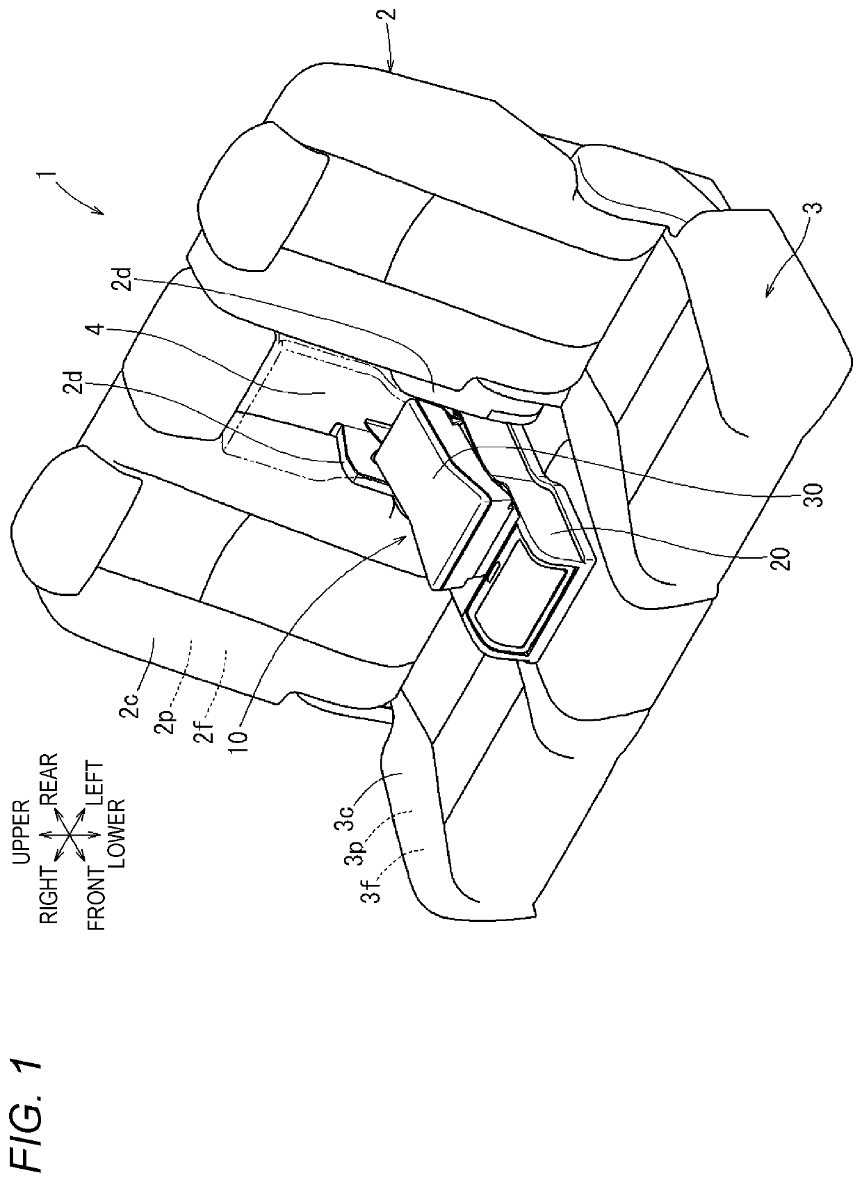
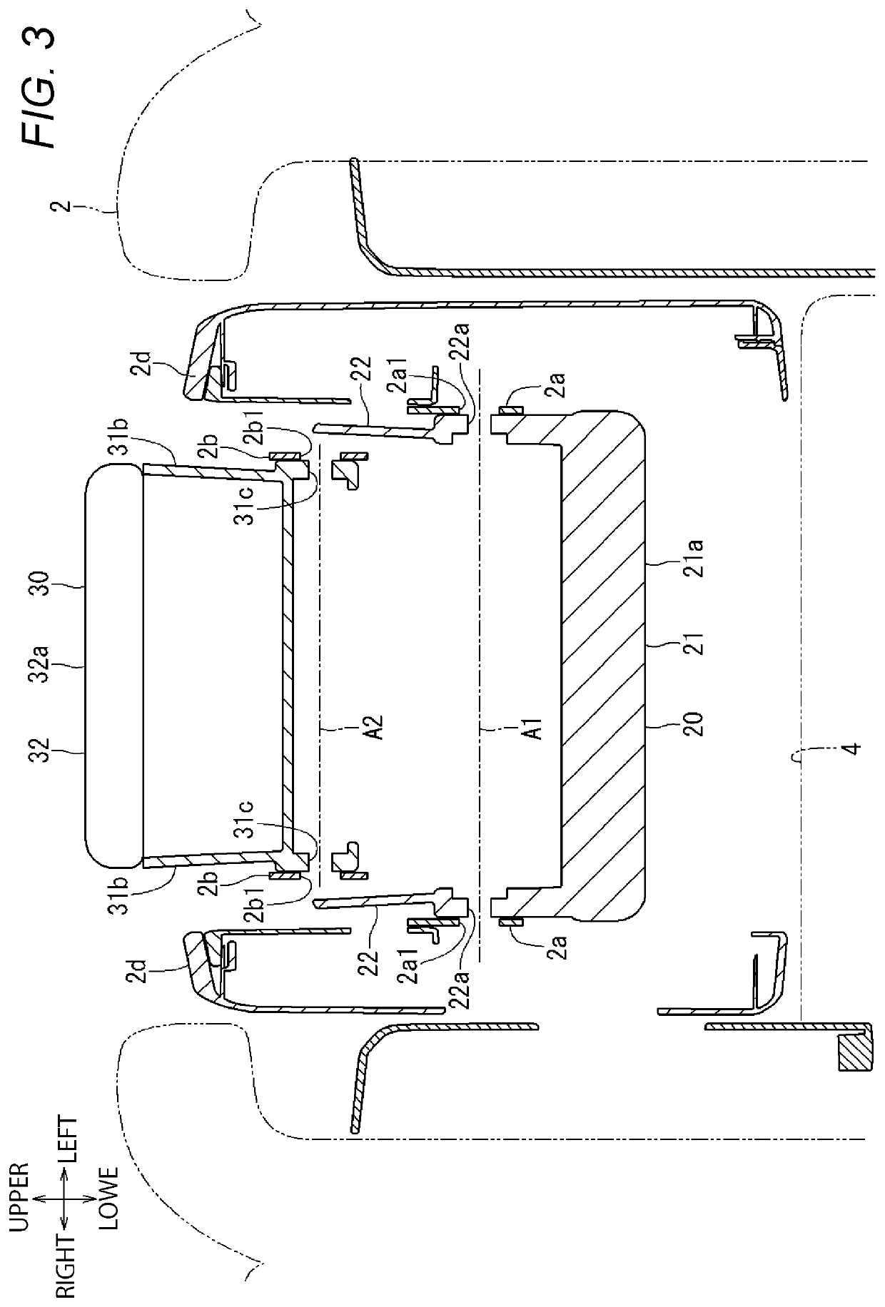
[0029]FIGS. 1 to 5 illustrate a first embodiment of the present disclosure. The first embodiment shows an example in which the present disclosure is applied to an armrest 10 attached to a seat back 2 of an automobile rear seat 1. In the drawings, directions when the automobile rear seat 1 is attached to an automobile are indicated by arrows. In the following description, descriptions of directions are made with reference to these directions. The automobile rear seat 1 including the seat back 2 to which the armrest 10 according to the present embodiment is attached is a bench seat and includes a seat cushion 3 serving as a seating portion and the seat back 2 serving as a backrest. The automobile rear seat 1 is attached to an automobile body. Here, the automobile rear seat 1 corresponds to “vehicle seat” in the claims.

[0030]As illustrated in FIG. 1, the seat cushion 3 includes a cushion frame 3f constituting a framework, a cushion pad 3p that is a cushion member, and a cushion cover 3...


PUM


Abstract

An armrest of a seat for a vehicle includes a first armrest that is movable between a storage position where the first armrest constitutes a part of a seating surface of a seat back and a use position where the first armrest abuts against and is supported on a seating surface of a seat cushion, a rear end portion of the first armrest in the use position being connected to a lower portion of the seat back to be rotatable forward and backward about a first rotation axis extending in a lateral direction of the seat, and a second armrest that is connected to the first armrest to be interlocked with the first armrest, is close to a rear side of the first armrest in the storage position, and is separated upward from the first armrest in the use position.

Description

CROSS REFERENCE TO RELATED APPLICATIONS[0001]This application is based on Japanese Patent Applications No. 2019-211111 filed on Nov. 22, 2019, the entire contents of which are incorporated herein by reference.TECHNICAL FIELD[0002]The present disclosure relates to an armrest of a vehicle seat.BACKGROUND ART[0003]A known armrest is rotatable relative to a seat back of a rear seat of a vehicle seat. JP-A-2018-118586 discloses an armrest capable of swinging forward and backward about a rotation shaft provided in a lower portion of the seat back between a storage position in which the armrest is stored in a seat back and a use position in which the armrest is laid down forward a seat. In the storage position in which the armrest is stored in a recess provided in a widthwise middle portion of the seat back, a front surface side of the armrest constitutes a portion of a seat surface of the seat back. In the use position in which the front surface side is abutted against a seat surface of a...

Claims


Application Information

Patent Timeline
Patent Type & Authority Patents(United States)
IPC IPC(8): B60N2/70B60N2/75B60N3/10
CPCB60N2/757B60N2/767B60N2/793B60N3/102B60N2/77B60N3/10
Inventor MORISHITA, KENTAROIIO, KAZUHIRO
Owner TOYOTA BOSHOKU KK
Learn More