Beverage dispenser with container engagement features

a beverage dispenser and container technology, applied in the field of beverage dispensers with container engagement, can solve the problems of air or other potentially damaging gasses or liquids entering the bottle, and achieve the effect of little or no effect on beverage quality

Active Publication Date: 2022-04-05
CORAVIN
View PDF24 Cites 1 Cited by
  • Summary
  • Abstract
  • Description
  • Claims
  • Application Information

AI Technical Summary

Benefits of technology

[0003]One or more embodiments in accordance with aspects of the invention allow a user to withdraw or otherwise extract a beverage, such as wine, from within a bottle that is sealed by a cork, plug, elastomeric septum or other closure without removing the closure. In some cases, removal of liquid from such a bottle may be performed one or more times, yet the closure may remain in place during and after each beverage extraction to maintain a seal for the bottle. Thus, the beverage may be dispensed from the bottle multiple times and stored for extended periods between each extraction with little or no effect on beverage quality. In some embodiments, little or no gas, such as air, which is reactive with the beverage may be introduced into the bottle either during or after extraction of beverage from within the bottle. Thus, in some embodiments, a user may withdraw wine from a wine bottle without removal of, or damage to, the cork, and without allowing air or other potentially damaging gasses or liquids entry into the bottle.
[0005]In some embodiments, a base of the device may include a clamp that is attached to the body and arranged to engage a container neck to secure the body relative to the container neck. For example, the clamp may include one or more clamp arms arranged to engage the container neck and secure the body so that lifting the body can lift both the body and the engaged container. This may allow a user to pour beverage from the container by manipulating the body alone. In other arrangements, the clamp may secure the body to the container so that the device is suspended from or otherwise secured to the container without other support. In some embodiments, the at least one clamp arm may define a receiving space with an entry opening at a bottom of the clamp to receive the container neck into the receiving space. That is, the container neck may be inserted into the receiving space by positioning the container neck into the entry opening at the bottom of the clamp and moving the container neck upwardly into the receiving space (or said another way, by positioning the entry opening over the container neck and moving the clamp downwardly onto the container neck). As an example, the container may be placed on a table top or other surface, and the container neck may be fully received into the receiving space of the clamp by inserting the container neck into the entry opening and moving the clamp downwardly relative to the container neck. In some embodiments, the at least one clamp arm may be spring biased to move relative to the base to exert an engagement force on the container neck when the neck is fully received in the receiving space. When receiving the container neck into the receiving space by moving the clamp downwardly onto the container, the at least one clamp arm may be moved against the spring bias so as to enlarge the receiving space and allow the container neck to be fully received.
[0006]In some embodiments, the at least one clamp arm includes a container engagement surface to aid in receiving and engaging with a container neck. For example, an engagement surface may extend vertically on an interior surface of a clamp arm and help guide movement of the container neck, as well as move the clamp arm relative to the base to allow for proper engagement of the container neck. In some embodiments, the engagement surface may have a lower portion that slopes inwardly and upwardly relative to the receiving space. The lower portion may be arranged to allow the clamp to be pushed downwardly on the container neck to receive the container neck in the receiving space and move the at least one clamp arm away from the container neck, e.g., against a spring bias on the clamp arm, while the at least one clamp arm exerts an engagement force on the container neck. In some cases, the lower portion of the container engagement surface may be arranged to contact a lip of the container neck such that the lower portion exerts a radially outward force on the at least one clamp arm to move the at least one clamp arm away from the lip of the container neck as the clamp is moved downwardly relative to the container neck to receive the container neck in the receiving space. In some cases, the container engagement surface includes an upper portion positioned above the lower portion that slopes outwardly and upwardly relative to the receiving space, e.g., such that the upper portion is arranged to disengage the clamp from a fully received container neck as the clamp is pulled upwardly relative to the container neck. The upper portion may exert a radially outward force on the at least one clamp arm to move the at least one clamp arm against the spring bias and away from the container neck as the clamp is moved upwardly relative to the container neck. Thus, the engagement surface may not only contact the container neck and exert a radially inward force on the container neck when in the receiving space to secure the container neck in place, but may allow the clamp to be engaged or disengaged from the container neck by moving the clamp and container relative to each other in a vertical direction.
[0017]In some embodiments, the controller may be arranged to control the at least one valve to dispense a defined amount of beverage from the container. For example, if a user tilts a bottle so as to conventionally pour from the bottle, the system may automatically dispense a defined amount of beverage, such as 6 ounces, and stop dispensing even if the bottle is kept in a pour orientation. To dispense another serving, the user may be required to put the bottle in a no-pour orientation and then again to a pour orientation. In some embodiments, the controller may be arranged to control the at least one valve in two modes including a first mode for maximized beverage dispensing speed and a second mode for minimized pressurized gas usage. This may allow a user to control the rate at which beverage is dispensed, or to conserve dispensing gas as needed.
[0018]In some embodiments, a container-mounted beverage dispensing system includes at least one conduit to deliver gas into a container holding a beverage and to receive beverage from the container for dispensing in a user's cup, and at least one valve to control gas flow into the container or beverage flow out of the container via the at least one conduit. Arrangements for the at least one conduit and valve discussed above may be employed, for example, such as single or multi-lumen needles, a gas control valve, a beverage control valve, etc. A container orientation sensor may detect rotation of the container about its longitudinal axis while in a pour orientation, and a controller may be arranged to control the at least one valve to prohibit gas or beverage flow in response to rotation of the container about the longitudinal axis while in the pour orientation. Thus, for example, a user may rotate a bottle about its longitudinal axis while the bottle is held in a pour orientation and the system may stop beverage dispensing and / or stop gas delivery into the bottle. This arrangement may help the user better stop dispensing and prevent dripping from the bottle. Such a control arrangement may be used with the feature of controlling dispensing based on a container's pour / no-pour orientation as discussed above, or used independently of such a feature.

Problems solved by technology

Thus, in some embodiments, a user may withdraw wine from a wine bottle without removal of, or damage to, the cork, and without allowing air or other potentially damaging gasses or liquids entry into the bottle.

Method used


Image

  • Beverage dispenser with container engagement features
  • Beverage dispenser with container engagement features
  • Beverage dispenser with container engagement features

Examples


Embodiment Construction

[0031]Aspects of the invention are described below with reference to illustrative embodiments, but it should be understood that aspects of the invention are not to be construed narrowly in view of the specific embodiments described. Thus, aspects of the invention are not limited to the embodiments described herein. It should also be understood that various aspects of the invention may be used alone and / or in any suitable combination with each other, and thus various embodiments should not be interpreted as requiring any particular combination or combinations of features. Instead, one or more features of the embodiments described may be combined with any other suitable features of other embodiments. For example, different clamp, latch and sensor configurations are discussed below, and it should be understood that various combinations of clamp, latch and / or sensor features may be made.

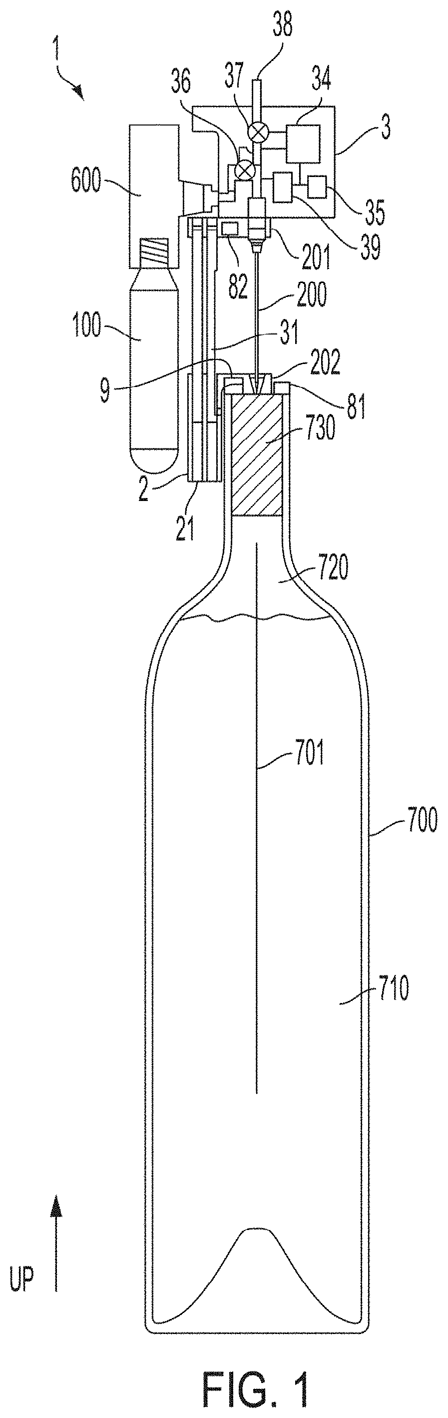
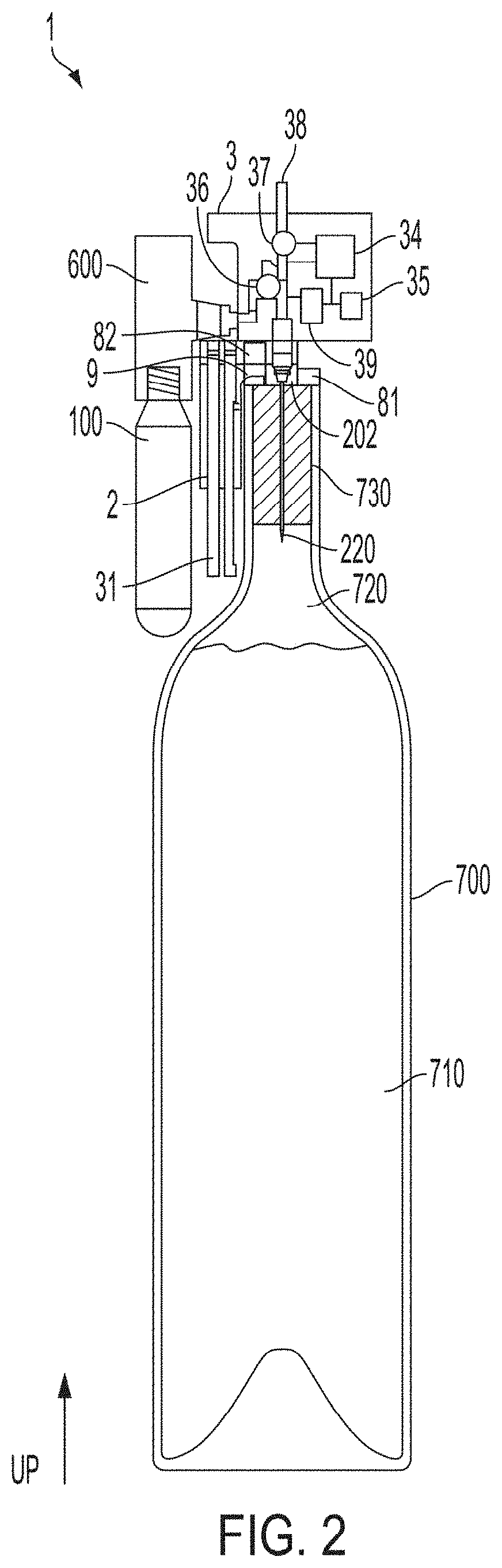
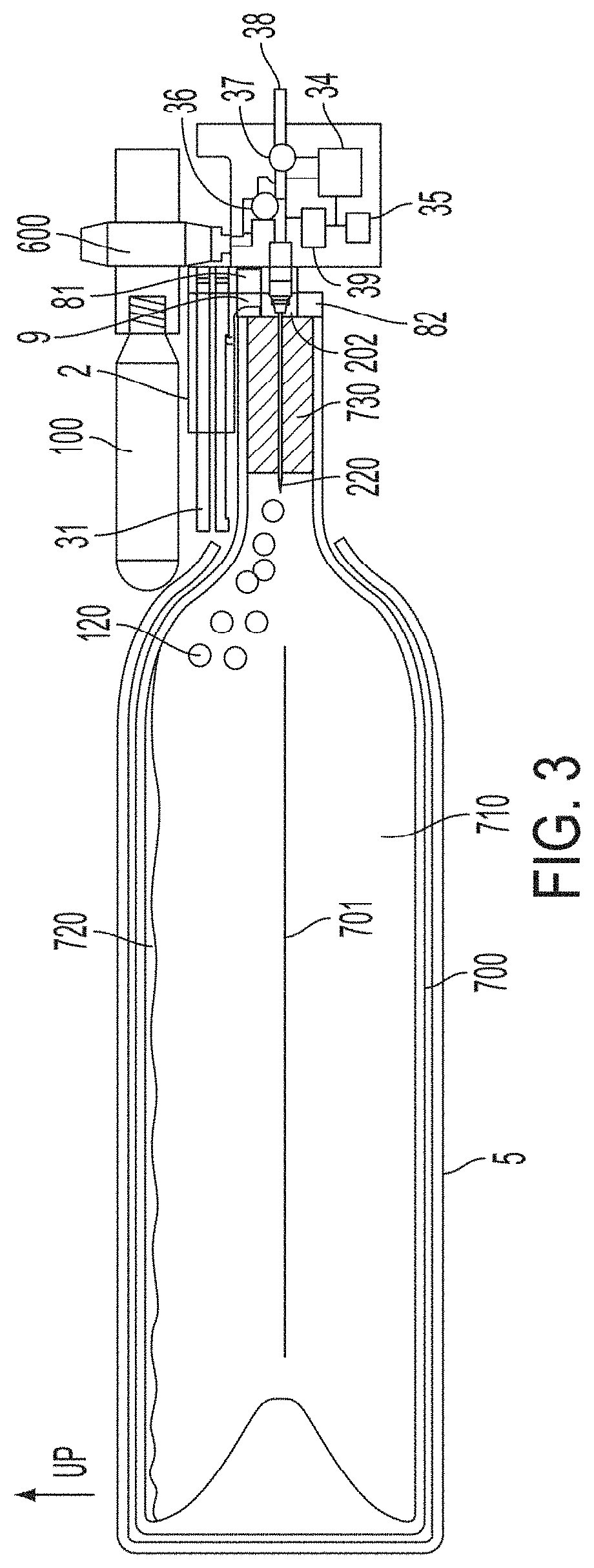
[0032]FIGS. 1-4 show schematic views of one embodiment of a beverage dispensing device (or extractor)...


PUM


Abstract

A clamp of the dispensing device may include a container engagement surface arranged to engage and / or disengage the clamp from the container neck when the clamp is pushed downwardly or pulled upwardly relative to the container neck. The container engagement surface may include a surface with a lower portion that slopes upwardly and inwardly, and an upper portion that slopes upwardly and outwardly relative to the container neck and that moves the clamp radially outwardly and away from the container neck as the clamp is moved vertically relative to the container neck. A latch may maintain a body portion of the dispensing device in an upper position, preventing needle insertion, until a container is suitably engaged with the base portion of the device, e.g., by a clamp. Sensors may detect engagement of a container with the device and / or insertion of a needle into the container.

Description

RELATED APPLICATION[0001]This Application claims priority under 35 U.S.C. § 119(e) to U.S. Provisional Application Ser. No. 62 / 611,952, filed Dec. 29, 2017, which is herein incorporated by reference in its entirety.BACKGROUND OF INVENTION[0002]This invention relates generally to the dispensing or other extraction of fluids from within a container, e.g., in the dispensing of wine from a wine bottle. Beverage dispensers, including devices arranged to clamp to a container, are described in U.S. Pat. Nos. 9,010,588 and 7,712,637.SUMMARY OF INVENTION[0003]One or more embodiments in accordance with aspects of the invention allow a user to withdraw or otherwise extract a beverage, such as wine, from within a bottle that is sealed by a cork, plug, elastomeric septum or other closure without removing the closure. In some cases, removal of liquid from such a bottle may be performed one or more times, yet the closure may remain in place during and after each beverage extraction to maintain a s...

Claims


Application Information

Patent Timeline
Patent Type & Authority Patents(United States)
IPC IPC(8): B67D1/04B67D1/08B67B7/00F16B2/10B67D1/00
CPCB67D1/0412B67B7/26B67D1/0802B67D1/0885B67D1/0888B67D1/0889F16B2/10B67D1/0418B67D2001/0098B67D2001/0481B67D2001/0487B67D2001/0812B67D2001/0825
Inventor RIDER, MICHAELDERUNTZ, OTTOLAMBRECHT, GREGORY
Owner CORAVIN
Why Eureka
Try Eureka