Water separator for a fuel cell system

a fuel cell and water separator technology, applied in electrochemical generators, lighting and heating apparatus, transportation and packaging, etc., can solve the problems of not having a corresponding overall height and not unlimited overall spa

Active Publication Date: 2022-04-05
AIRBUS OPERATIONS GMBH
View PDF20 Cites 0 Cited by
  • Summary
  • Abstract
  • Description
  • Claims
  • Application Information

AI Technical Summary

Benefits of technology

[0008]The water separator according to an embodiment of the invention is consequently endowed with a significantly flatter design shape than the usual water separators previously described, of a largely canister-shaped formation. Owing to the relatively large inside width compared to the overall height, this consequently results in a water separator of a very shallow construction, the housing volume of which extends from the base plate towards the gas connection and furthermore tapers in this direction. The degree of taper causes the rate at which the level rises to increase as the quantity of water increases. In continuous, uniform filling of the housing, the level consequently rises ever more rapidly when the tapering area is reached and filled. By suitably locating a level sensor in the tapering area, a predefined quantity of water can therefore be resolved and detected very reliably. This makes it possible to determine a precise starting time for a water drainage process. Removing the water on the base plate through the drainage outlet leads initially to a rapid and then to a slowing fall in the level. The level falls slowest in the area of the base plate. It is advisable to set a time control for discontinuing the water drainage process such that a residual quantity of water still remains, which covers the drainage outlet. Due to the low rate at which the level moves in the vicinity of the base plate, a residual level remaining after drainage of the water can be adjusted very precisely by setting the time duration.
[0014]The water separator could further comprise a flow-stilling element, which is arranged in the housing at a distance from the base plate and spans a local cross section of the housing. The flow-stilling element serves to still gas flows inside the housing in such a way that the water already present in the water separator is not flushed away from a spatial area surrounding the drainage outlet but remains there and prevents a gas flowing out of the drainage outlet. The flow-stilling element could extend, for example, over the entire cross section of the housing, so that all flows directed out of the gas connection towards the base plate can be reliably stilled.
[0016]The flow-stilling element could define the first portion. This serves to still the quantity of water received, particularly in the first portion, and to prevent heavy flows and the formation of a 2-phase mixture or 2-phase flow (gas and liquid) in an area surrounding the drainage outlet.

Problems solved by technology

At the same time, however, the overall space is not unlimited, so that there is not a corresponding overall height available, particularly for canister-like water separators affording sufficient capacity.

Method used


Image

  • Water separator for a fuel cell system
  • Water separator for a fuel cell system
  • Water separator for a fuel cell system

Examples


Embodiment Construction

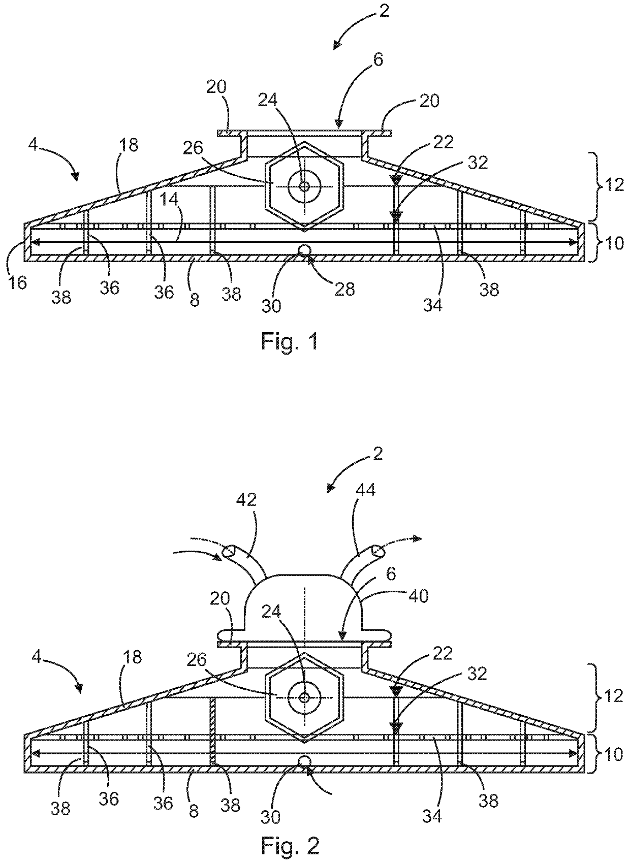
[0030]FIG. 1 shows a side view of a water separator 2 for a fuel cell system. The water separator 2 may be of rotationally symmetrical design, so that the representation is to be regarded as a median section. Alternatively, however, the water separator 2 may also be formed by a non-circular body and be extended vertically to the drawing plane with a uniform cross section.

[0031]The water separator 2 comprises a closed housing 4 having a gas connection 6 and a base plate 8 arranged remotely from the gas connection 6. This forms a first portion 10 and a second portion 12 lying above the latter. In the first portion 10 an inside width 14, i.e. the width of the housing 4 in the interior of the housing 4, is constant and represents a maximum compared to the second portion 12. In the second portion 12, which is situated between the first portion 10 and the gas connection 6, the inside width 14 diminishes continuously in the direction of the gas connection 6. In the exemplary embodiment sho...


PUM

PropertyMeasurementUnit
angleaaaaaaaaaa
angleaaaaaaaaaa
angleaaaaaaaaaa

Abstract

A water separator for a fuel cell system includes a closed housing with a gas connection, and a base plate arranged remotely from the gas connection and having a drainage outlet, an inside width of the housing at least in portions decreasing from the base plate towards the gas connection, and the height of the housing being less than the greatest inside width of the housing.

Description

FIELD OF THE INVENTION[0001]The invention relates to a water separator for a fuel cell system, a fuel cell system having such a water separator and a vehicle having a fuel cell system and such a water separator.BACKGROUND OF THE INVENTION[0002]In the operation of fuel cells water in the form of water vapour always accumulates as by-product. For reasons of weight and economic efficiency it is advisable, particularly when using a fuel cell in an aircraft, to separate the water and deliver it to other consumer units. Elongated, substantially cylindrical, canister-shaped water separators are known, which have a fluid connection to an exhaust or recirculation line of a fuel cell. Due to a relatively high pressure level of a gas-water vapour mixture flowing in the exhaust or recirculation line, this mixture may be supersaturated, so that water readily “falls” into the water separator. Failing this, the exhaust or recirculation line can be cooled, so that water vapour condenses out. It the...

Claims


Application Information

Patent Timeline
Patent Type & Authority Patents(United States)
IPC IPC(8): H01M8/04H01M8/04119
CPCH01M8/04164H01M2250/20H01M8/04156H01M8/2475H01M2008/1095H01M8/0662B64D2041/005F22B1/003F16T1/34Y02E60/50Y02T90/40
Inventor WOLFF, CHRISTIANKURRE, JENS-DIETRICH
Owner AIRBUS OPERATIONS GMBH
Why Eureka
Try Eureka